


Wideband Test Amplifier

Description: This single-stage amplifier, utilizing a 2N2222 or 2N3904 general-purpose transistor, is designed for interfacing with test instruments. The transformer T1 is an Amidon Associates FT-23-43 core, wound with 17 turns of #26 wire for the primary and 6 turns for the secondary. J3 serves as a lower-level output for monitoring devices, such as a receiver frequency counter or spectrum analyzer.
This single-stage amplifier circuit is an essential component for enhancing signal levels in various testing applications. The choice of transistors, either the 2N2222 or 2N3904, provides flexibility and reliability, as both are widely used in low-power amplification due to their favorable characteristics, including high gain and low noise.
The transformer T1, constructed with an Amidon Associates FT-23-43 core, plays a crucial role in the circuit by providing impedance matching and signal isolation. The primary winding consists of 17 turns of #26 wire, while the secondary winding features 6 turns. This configuration allows for effective voltage transformation, enabling the amplifier to boost the input signal to a level suitable for the output monitoring device.
The output jack J3 is specifically designed for connecting to lower-level monitoring devices, such as a receiver frequency counter or a spectrum analyzer. This output provides a convenient means to observe the amplified signal without introducing significant loading effects on the circuit. The design ensures that the amplifier maintains signal integrity while delivering sufficient output for accurate measurements.
Overall, this single-stage amplifier circuit is a valuable tool for engineers and technicians working with test instruments, offering an efficient solution for signal amplification and monitoring. This single-stage amplifier (using a 2N2222 or 2N3904 general-purpose transistor) is useful for interfacing test in struments. T1 is an Amidon Associates FT-23-43 core wound with 17 and 6 turns of #26 wire. J3 is a lower-level output for a monitoring device (such as a receiver frequency counter or spectrum analyzer).
This single-stage amplifier circuit is an essential component for enhancing signal levels in various testing applications. The choice of transistors, either the 2N2222 or 2N3904, provides flexibility and reliability, as both are widely used in low-power amplification due to their favorable characteristics, including high gain and low noise.
The transformer T1, constructed with an Amidon Associates FT-23-43 core, plays a crucial role in the circuit by providing impedance matching and signal isolation. The primary winding consists of 17 turns of #26 wire, while the secondary winding features 6 turns. This configuration allows for effective voltage transformation, enabling the amplifier to boost the input signal to a level suitable for the output monitoring device.
The output jack J3 is specifically designed for connecting to lower-level monitoring devices, such as a receiver frequency counter or a spectrum analyzer. This output provides a convenient means to observe the amplified signal without introducing significant loading effects on the circuit. The design ensures that the amplifier maintains signal integrity while delivering sufficient output for accurate measurements.
Overall, this single-stage amplifier circuit is a valuable tool for engineers and technicians working with test instruments, offering an efficient solution for signal amplification and monitoring. This single-stage amplifier (using a 2N2222 or 2N3904 general-purpose transistor) is useful for interfacing test in struments. T1 is an Amidon Associates FT-23-43 core wound with 17 and 6 turns of #26 wire. J3 is a lower-level output for a monitoring device (such as a receiver frequency counter or spectrum analyzer).

Simple Transistor Amplifier Circuit Schematic and Explanation
This circuit does not function as effectively as it could. It was created when the designer had a limited understanding of circuit design. An improved schematic will be developed and posted later, featuring a better design. The schematic indicates "antenna,"...

The NOT gate
The single-transistor inverter circuit discussed earlier is too simplistic for practical use as a gate. Real inverter circuits utilize multiple transistors to enhance voltage gain, ensuring that the final output transistor is either in full cutoff or full saturation, while...

Basic transistor amplifier circuits
Typical component values are provided for use at audio frequencies, where these circuits are most commonly utilized. The input and output phase relationships are illustrated.
The circuit design focuses on audio frequency applications, emphasizing the selection of component values that optimize...

Bipolar Transistor HBridge Motor Driver
Schematic, breadboard photo, parts list, and results of several transistor variations on the classic bipolar H-bridge motor driver circuit.
The classic bipolar H-bridge motor driver circuit is a widely used configuration that allows for the control of DC motors in both...
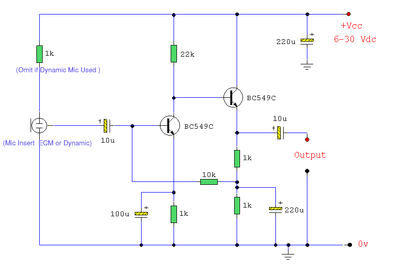
ECM Mic Preamplifier
Both transistors should be low noise types. In the original circuit, BC650C was used, which is an ultra-low noise device. These transistors are now hard to find, but BC549C or BC109C are good replacements. The circuit is self-biasing and will...

Multi-Zone Transistor-Based Intruder Alarm
This is a simple transistor-based burglar alarm circuit. Its features include automatic exit and entry delays, along with a timed bell cut-off and reset. It is designed to be used with standard types of normally-closed input devices such as magnetic...
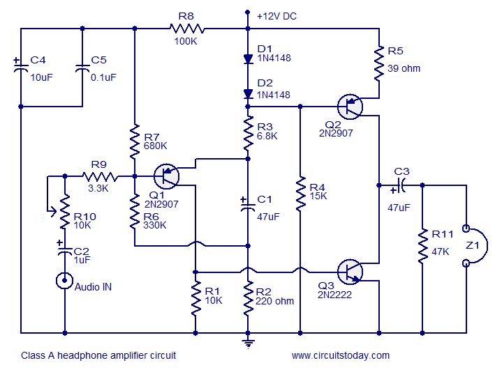
Transistor amplifier circuits
Transistor amplifier circuits that are simple and easy to construct. This includes a headphone amplifier, a four-transistor amplifier, and a low-power amplifier.
Transistor amplifier circuits are fundamental components in electronic design, offering various applications ranging from audio amplification to signal processing....

Long-Duration Time Delay
Transistor Q1 and resistors R1, R2, and R3 form a constant current source, with the charge current adjustable to as low as a few nanoamperes. This current is insufficient to activate the UJT, where IP is 0.2 A, unless a...

Vehicle Detector
A simple single-transistor Colpitts oscillator is depicted in the schematic. When a vehicle passes over the loop, the inductance decreases, resulting in an increase in the oscillator frequency. A microprocessor measures the oscillator frequency and takes appropriate actions based on...