


With FET amplifier output transformer circuit
#FET amplifier
#output transformer
#tube amp
#audio amplifier
#transistor circuits
#sound quality
#tone control
#electronic circuits

Description: This article describes a transformer-based output FET amplifier, with tonal characteristics similar to those of tube amplifiers. It introduces various effects that are significant for audio enthusiasts. Power amplifier specifications include a rated output power of 50W (with an 8Ω load), a frequency response of 40Hz to 25kHz with a flat curve, harmonic distortion measured at 0.5% (at 1kHz), a signal-to-noise ratio (SNR) of 90dB, and an input sensitivity of 800mV. The power amplifier utilizes a double differential amplifier configuration with a preamp and an output transformer in the FET power amplifier stage, adhering to the "simplicity first" design principle. The circuit features a pair of NPN transistors (V1, V2) forming the first differential amplifier, while another pair of PNP transistors constitutes the second differential amplifier through mutual diodes (V3, V4). This arrangement, which employs transistors of different conductivity types, enhances power supply voltage utilization and improves thermal stability. Resistors R5 and R6 are configured to provide a two-way exchange of negative feedback, ensuring complementary symmetry within the circuit. This design promotes good DC stability and minimizes distortion, resulting in a wide frequency response. The output from the preceding stage (V3, V4) has opposite polarity at the collector, functioning as a complementary push-pull power amplification stage, with reference waveforms derived from two opposing odd signal sources.
The described transformer-based output FET amplifier is engineered to deliver high-fidelity audio reproduction, closely resembling the warm tonal qualities associated with traditional tube amplifiers. The design incorporates a transformer that plays a critical role in impedance matching and signal coupling, facilitating efficient power transfer while maintaining audio integrity.
The power amplifier's rated output of 50W at an 8Ω load ensures compatibility with a wide range of speakers, making it suitable for various audio applications. The frequency response extending from 40Hz to 25kHz allows the amplifier to reproduce low bass notes and high-frequency details effectively, contributing to a balanced audio output.
Harmonic distortion is kept to a minimum at 0.5% when measured at 1kHz, which is crucial for preserving the clarity and naturalness of the audio signal. The SNR of 90dB indicates that the amplifier can produce a clean sound with minimal background noise, enhancing the listening experience.
The double differential amplifier configuration is pivotal in achieving high performance. By utilizing both NPN and PNP transistors, the design capitalizes on their complementary characteristics, which not only improves voltage utilization but also enhances the thermal stability of the amplifier. This is particularly important in audio applications where temperature fluctuations can affect performance.
Negative feedback provided by resistors R5 and R6 plays a significant role in stabilizing the circuit and reducing distortion. This feedback mechanism contributes to the overall linearity of the amplifier, ensuring that the output signal closely follows the input signal without unwanted alterations.
In summary, this transformer-based output FET amplifier exemplifies a well-thought-out design that prioritizes simplicity, stability, and audio fidelity. Its robust specifications make it an excellent choice for audio enthusiasts seeking a reliable amplifier with tube-like tonal qualities.This article describes a transformer with output FET amplifier production, its tone has been very close to the tube amp effects introduced to the circuit for the majority of audio enthusiasts reference. Power amplifier Specifications: Rated output power: 50w (load 8n); Frequency response: 4 0Hz ~ 25Hz curve flat; harmonic distortion: 0.5 (measured under lkHz); SNR: 90d13; input sensitivity: 800n1V o the power amplifier by a double differential amplifier with a preamp and output transformer FET power amplifier stage configuration, the design idea of "simplicity first" principle. Figure 7-15 can be seen from a pair of NPN type transistor Vl.v2 constitutes a first differential amplifier, the other a pair of PNP type.
Mutual diode V3, V4 constitute _r second differential amplifier. Two different conductivity type transistors increases the power supply voltage utilization, but have different temperature characteristics, so that significantly improve the stability of the whole machine. FIG resistors R5, R6-oriented stage circuit provides a two-way exchange of negative feedback, and the circuit full complementary symmetry, so good DC stability of the circuit, while reducing the degree of distortion, wide forehead noon.
Circuit the output of the preceding stage V3, V4 polarity opposite the collector, as a complementary push-pull power amplifying stage after the reference waveforms for the two opposite odd signal source
The described transformer-based output FET amplifier is engineered to deliver high-fidelity audio reproduction, closely resembling the warm tonal qualities associated with traditional tube amplifiers. The design incorporates a transformer that plays a critical role in impedance matching and signal coupling, facilitating efficient power transfer while maintaining audio integrity.
The power amplifier's rated output of 50W at an 8Ω load ensures compatibility with a wide range of speakers, making it suitable for various audio applications. The frequency response extending from 40Hz to 25kHz allows the amplifier to reproduce low bass notes and high-frequency details effectively, contributing to a balanced audio output.
Harmonic distortion is kept to a minimum at 0.5% when measured at 1kHz, which is crucial for preserving the clarity and naturalness of the audio signal. The SNR of 90dB indicates that the amplifier can produce a clean sound with minimal background noise, enhancing the listening experience.
The double differential amplifier configuration is pivotal in achieving high performance. By utilizing both NPN and PNP transistors, the design capitalizes on their complementary characteristics, which not only improves voltage utilization but also enhances the thermal stability of the amplifier. This is particularly important in audio applications where temperature fluctuations can affect performance.
Negative feedback provided by resistors R5 and R6 plays a significant role in stabilizing the circuit and reducing distortion. This feedback mechanism contributes to the overall linearity of the amplifier, ensuring that the output signal closely follows the input signal without unwanted alterations.
In summary, this transformer-based output FET amplifier exemplifies a well-thought-out design that prioritizes simplicity, stability, and audio fidelity. Its robust specifications make it an excellent choice for audio enthusiasts seeking a reliable amplifier with tube-like tonal qualities.This article describes a transformer with output FET amplifier production, its tone has been very close to the tube amp effects introduced to the circuit for the majority of audio enthusiasts reference. Power amplifier Specifications: Rated output power: 50w (load 8n); Frequency response: 4 0Hz ~ 25Hz curve flat; harmonic distortion: 0.5 (measured under lkHz); SNR: 90d13; input sensitivity: 800n1V o the power amplifier by a double differential amplifier with a preamp and output transformer FET power amplifier stage configuration, the design idea of "simplicity first" principle. Figure 7-15 can be seen from a pair of NPN type transistor Vl.v2 constitutes a first differential amplifier, the other a pair of PNP type.
Mutual diode V3, V4 constitute _r second differential amplifier. Two different conductivity type transistors increases the power supply voltage utilization, but have different temperature characteristics, so that significantly improve the stability of the whole machine. FIG resistors R5, R6-oriented stage circuit provides a two-way exchange of negative feedback, and the circuit full complementary symmetry, so good DC stability of the circuit, while reducing the degree of distortion, wide forehead noon.
Circuit the output of the preceding stage V3, V4 polarity opposite the collector, as a complementary push-pull power amplifying stage after the reference waveforms for the two opposite odd signal source

2x30watt home amplifier circuit
The audio amplifier circuit is highly suitable for home use, particularly with subwoofer or woofer speakers. Commonly referred to as a home amplifier, these audio amplifiers are based on integrated circuits (ICs), specifically the STK series, which includes models such...

Integrated operational amplifier tone control circuit of a simplified equivalent circuit a
At high frequencies, the capacitor Cz can be considered a short circuit (i.e., the resistance of the RPi is negligible). This is illustrated in Figure 4-6 (a) of the apparatus, which corresponds to the equivalent circuit shown in Figure 4-6...

TDA2030AL-TA5-T 18W Hi-Fi Audio Power Amplifier And 35W Driver
The TDA2549 is a complete intermediate frequency (IF) circuit that includes automatic frequency control (AFC), automatic gain control (AGC), demodulation, and video preamplification capabilities for multistandard television receivers. It can process both positively and negatively modulated video signals in color...

Tone Controls
The circuit operates from a 12V or similar power supply, with the option to adjust resistor R1 for higher voltage applications. There is significant flexibility in selecting values for components like capacitor C1. At point B, VR1 serves as a...
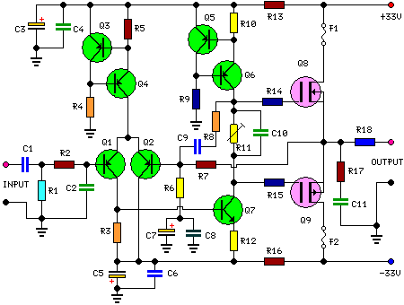
25 Watt Audio Amplifier Circuit
This is a 25-watt basic power amplifier designed for ease of construction at a reasonable cost. It outperforms the standard STK module amplifiers commonly found in mass-market stereo receivers today. The design was initiated to create a 25-watt amplifier for...

Low noise tone control circuit using C945
If you have old electronic equipment that has been around for many years, it is beneficial to build a good electronic project. Guidance is requested regarding a pre-tone control circuit for this purpose.
A pre-tone control circuit is an essential component...

Car 20W audio booster amplifier
This circuit is a 20W Audio Amplifier kit, based on the TDA2005 IC, a class B dual audio amplifier, specifically designed for car radio applications etc. Power supply - 18 VDC. Output power - 20 W, 4 ?. IC built...

Mini Class A Audio Amplifier
The philosophy behind this minimalist design has been explained by Flavio Dellepiane on his highly interesting site. I have myself written an article about this fleapower amp from Italy in the American magazine AudioXpress. All relevant details are published there....
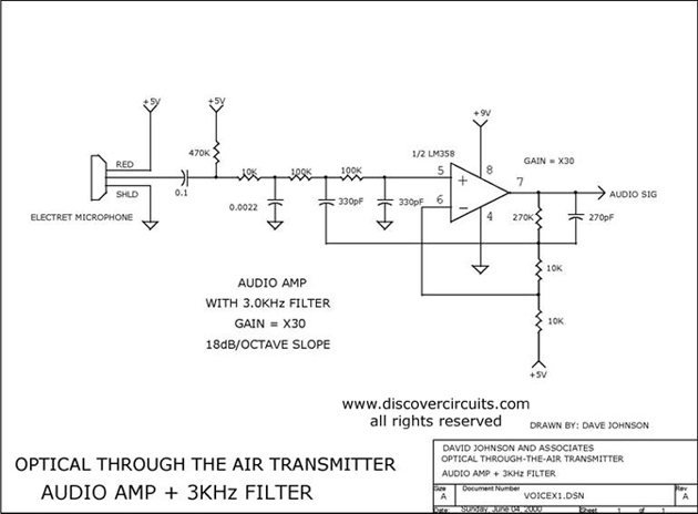
AUDIO AMP + 3KHz FILTER
Audio amplifier with a 3 kHz filter. This circuit serves as the audio amplification section for a complete optical transmitter. It amplifies and filters voice audio signals from an electret microphone.
The audio amplifier circuit is designed to enhance the weak...