


Arduino Calibration

Description: This example demonstrates a technique for calibrating sensor input. The Arduino takes sensor readings for five seconds during startup and tracks the highest and lowest values obtained. These sensor readings during the first five seconds of the sketch execution define the minimum and maximum expected values for the readings taken during the loop. Connect an LED to digital pin 9 with a 220-ohm current-limiting resistor. Connect a photocell to 5V and then to analog pin 0 with a 10K-ohm resistor as a reference to ground. Initially, the minimum is set high, and readings lower than that are saved as the new minimum. Similarly, the maximum is set low, and readings higher than that are saved as the new maximum.
The described circuit involves an Arduino microcontroller configured to calibrate sensor inputs effectively. During the initialization phase, the system collects analog readings from a photocell, also known as a light-dependent resistor (LDR), for five seconds. This time frame allows the Arduino to establish baseline values for environmental light conditions. The highest and lowest readings recorded during this period set the thresholds for subsequent readings in the main loop of the program.
To implement this circuit, an LED is connected to digital pin 9 of the Arduino through a 220-ohm resistor, which serves to limit the current and protect the LED from excessive voltage. The photocell is connected in a voltage divider configuration with a 10K-ohm resistor. One terminal of the photocell is connected to the 5V power supply from the Arduino, and the other terminal connects to analog pin 0, which reads the voltage across the photocell and the resistor combination. The other end of the 10K-ohm resistor is grounded, completing the circuit.
In operation, the Arduino continuously monitors the voltage at analog pin 0. During the initial five seconds, the program compares each reading against the established minimum and maximum values. If a reading falls below the minimum, it updates the minimum threshold; conversely, if a reading exceeds the maximum, it updates the maximum threshold. This calibration process allows the system to adapt to varying lighting conditions, ensuring accurate sensor readings throughout its operation.
This configuration is beneficial in applications where precise light measurements are critical, such as in automatic lighting systems or environmental monitoring setups. The use of a photocell allows the circuit to respond dynamically to changes in ambient light, while the LED provides visual feedback or can serve as an indicator for system status or alerts.This example demonstrates one techinque for calibrating sensor input. The Arduino takes sensor readings for five seconds during the startup, and tracks the highest and lowest values it gets. These sensor readings during the first five seconds of the sketch execution define the minimum and maximum of expected values for the readings taken during th
e loop. Connect an LED to digital pin 9 with a 220 ohm current limiting resistor. Connect a photocell to 5V and then to analog pin 0 with a 10K ohm resistor as a reference to ground. These may seem backwards. Initially, you set the minimum high and read for anything lower than that, saving it as the new minimum. Likewise, you set the maximum low and read for anything higher as the new maximum, like so:
The described circuit involves an Arduino microcontroller configured to calibrate sensor inputs effectively. During the initialization phase, the system collects analog readings from a photocell, also known as a light-dependent resistor (LDR), for five seconds. This time frame allows the Arduino to establish baseline values for environmental light conditions. The highest and lowest readings recorded during this period set the thresholds for subsequent readings in the main loop of the program.
To implement this circuit, an LED is connected to digital pin 9 of the Arduino through a 220-ohm resistor, which serves to limit the current and protect the LED from excessive voltage. The photocell is connected in a voltage divider configuration with a 10K-ohm resistor. One terminal of the photocell is connected to the 5V power supply from the Arduino, and the other terminal connects to analog pin 0, which reads the voltage across the photocell and the resistor combination. The other end of the 10K-ohm resistor is grounded, completing the circuit.
In operation, the Arduino continuously monitors the voltage at analog pin 0. During the initial five seconds, the program compares each reading against the established minimum and maximum values. If a reading falls below the minimum, it updates the minimum threshold; conversely, if a reading exceeds the maximum, it updates the maximum threshold. This calibration process allows the system to adapt to varying lighting conditions, ensuring accurate sensor readings throughout its operation.
This configuration is beneficial in applications where precise light measurements are critical, such as in automatic lighting systems or environmental monitoring setups. The use of a photocell allows the circuit to respond dynamically to changes in ambient light, while the LED provides visual feedback or can serve as an indicator for system status or alerts.This example demonstrates one techinque for calibrating sensor input. The Arduino takes sensor readings for five seconds during the startup, and tracks the highest and lowest values it gets. These sensor readings during the first five seconds of the sketch execution define the minimum and maximum of expected values for the readings taken during th
e loop. Connect an LED to digital pin 9 with a 220 ohm current limiting resistor. Connect a photocell to 5V and then to analog pin 0 with a 10K ohm resistor as a reference to ground. These may seem backwards. Initially, you set the minimum high and read for anything lower than that, saving it as the new minimum. Likewise, you set the maximum low and read for anything higher as the new maximum, like so:

Make an Atom Synchronised Clock from a 1950s Slave Dial using Arduino
Upon purchasing the slave dial, it arrived without instructions, packaging, or additional details. The only visible markings, aside from decades of grime, were on the face (SMITH SECTRIC, ACELEC SYDNEY) and some markings on the bracket holding the mechanism (E....
Arduino Shift Out
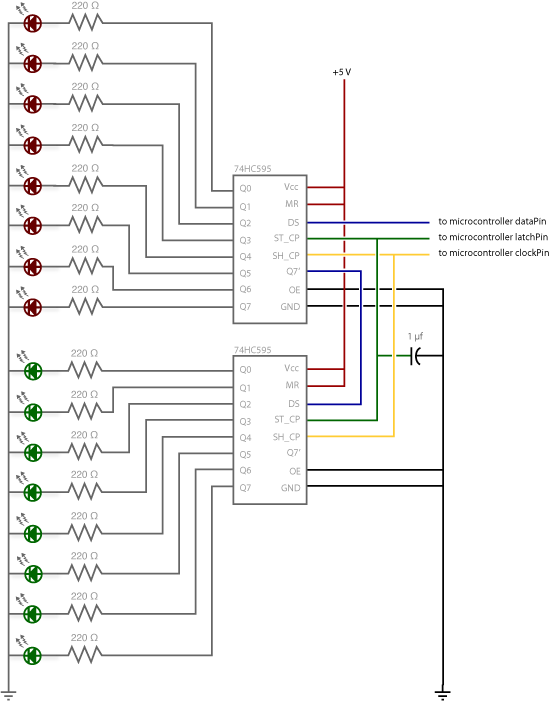
At some point, it may be necessary to extend the number of pins on an Arduino board using shift registers. This example utilizes the 74HC595, which is described in the datasheet as an "8-bit serial-in, serial or parallel-out shift register...

Arduino board
If you are interested in working with Arduino, you may have considered creating your own Arduino board.
Creating a custom Arduino board can be an enriching project that allows for greater flexibility and personalization in electronic designs. The process typically involves...

Arduino Producing DTMF Tones
The project involves teaching an Arduino to generate DTMF (Dual-Tone Multi-Frequency) tones using the HT9000A DTMF chip. These tones are the familiar "touch tones" used in telephone systems. The output volume from the chip is low, suggesting the need for...

arduino How can I display a scoreboard on stage for a play
A scoreboard is located in the center of the room, which will be controlled from backstage. The scoreboard features two individual 3-digit numbers. Whenever the score changes, a sound will be emitted. The simplest, most efficient, and cost-effective solution identified...

Field disturbance sensor-alarm
The change in ambient light triggers the alarm by changing the resistance of LDR1 and LDR2.
The circuit utilizes two light-dependent resistors (LDR1 and LDR2) to detect variations in ambient light levels. LDRs are passive components that exhibit a change in...

midi to dmx arduino control shield
A simple Arduino MIDI-to-DMX control was created for a robot band named Science Fiction Children. The setup consists of two inexpensive LED Par56 lights from Stairville, a basic DMX dimmer pack, and Ableton Live for sound management. The objective is...

Arduino Controls an Infrared Helicopter
The 2N3904 is an NPN transistor. When observing the flat face of the transistor, the left lead is the Emitter (pin 1 in the schematic), the middle lead is the Base (pin 2 in the schematic), and the right lead...

Remote-controlled fiber-optic Ceiling Light with Arduino
A wooden table features numerous holes of varying diameters designed to accommodate optical fibers. Due to the size of the ceiling lamp (90 cm x 60 cm), it was not feasible to utilize a single bundle of fibers, resulting in...