


Arduino Mega 512 kB SRAM expansion shield
#arduino mega
#sram expansion
#memory
#gps disciplined oscillator
#qp state machine
#c++ programming
#stl library
#microcontroller

Description: Programming the GPS Disciplined Oscillator (GPSDO) with the QP state machine framework has revealed that the Arduino Mega 2560 system has run out of SRAM. This is not surprising given the limited 8 kB available, especially when programming in C++ with an STL library port. A potential solution comes from Andy Brown, who offers a 512 kB SRAM expansion for the Arduino Mega. However, the design requires modifications to fit a full-sized Arduino Mega shield instead of a board that sticks off the side. A new layout has been created for the SRAM memory expansion to serve as an Arduino Mega-sized expansion board. The modified circuit retains the original design but features appropriate pin connections for a complete Mega shield. Current designs for the shield PCB are also available. Although the layout may not be aesthetically pleasing, it meets the necessary requirements, and prototypes are being prepared. There is an opportunity for beta testers to receive a prototype board at a cost of approximately US$10, excluding postage and handling.
The proposed design involves a SRAM expansion board tailored for the Arduino Mega 2560, aimed at enhancing the memory capacity for applications such as GPSDO programming. The original design by Andy Brown has been adapted to create a full-sized shield that integrates seamlessly with the Mega's architecture. The expansion board is equipped with a 512 kB SRAM chip, which significantly increases the available memory for complex applications, allowing for more extensive libraries and functionalities.
The schematic of the board includes essential components such as the SRAM chip, voltage regulators to ensure stable power supply, and appropriate decoupling capacitors to minimize noise. The pin layout is designed to match the Arduino Mega's GPIO configuration, ensuring that all necessary connections, including power, ground, and data lines, are accessible without interference. The PCB design incorporates standard practices for routing, including ground planes for signal integrity and careful consideration of trace widths to handle the expected current loads.
Prototyping efforts will focus on verifying the functionality of the memory expansion, ensuring compatibility with existing Arduino libraries, and assessing the performance of the additional SRAM in real-world applications. Beta testers will be provided with prototype boards to evaluate the design's effectiveness in various use cases, with feedback utilized to refine future iterations of the product. The anticipated cost structure aims to cover manufacturing expenses while allowing for further development of the expansion board.Programming the GPS Disciplined Oscillator (GPSDO) with the QP state machine framework -, which I badly need to write up - has led to the conclusion that I`ve run out of SRAM on the the Arduino Mega 2560 system. Not surprising given that there`s only(!) 8 kB available and I`m programming in C+ with an STL library port, etc.
So what to do Well i t would seem that Andy Brown - andybrown. me. uk - again provides the solution with his 512 kB SRAM expansion for the Arduino Mega. Either he`s omniscient or, more likely, he`s "been there and done that!" However I want to be able to mount everything and a board sticking off the side - as detailed in Andy`s design - doesn`t meet the need. So I`ve re-laid out the SRAM memory expansion to be an Arduino Mega sized expansion board. Figure 1 shows the modified circuit, exactly the same as the original design but with suitable pin connections for a full Mega shield.
Figures 2a and 2b meanwhile are the current design for the shield PCB. I doubt the layout will win any competitions for a PCB layout, but everything is there and now I`m working to get some prototypes made up. I`m looking for a couple of beta (alpha ) testers. If you`re interested in receiving a prototype board - noting that it is a prototype and not at all tested - then let me know!
Cost to you will be whatever it costs me on a per board basis, plus postage and handling. Currently it looks likes each board will cost US$10 excluding postage.
The proposed design involves a SRAM expansion board tailored for the Arduino Mega 2560, aimed at enhancing the memory capacity for applications such as GPSDO programming. The original design by Andy Brown has been adapted to create a full-sized shield that integrates seamlessly with the Mega's architecture. The expansion board is equipped with a 512 kB SRAM chip, which significantly increases the available memory for complex applications, allowing for more extensive libraries and functionalities.
The schematic of the board includes essential components such as the SRAM chip, voltage regulators to ensure stable power supply, and appropriate decoupling capacitors to minimize noise. The pin layout is designed to match the Arduino Mega's GPIO configuration, ensuring that all necessary connections, including power, ground, and data lines, are accessible without interference. The PCB design incorporates standard practices for routing, including ground planes for signal integrity and careful consideration of trace widths to handle the expected current loads.
Prototyping efforts will focus on verifying the functionality of the memory expansion, ensuring compatibility with existing Arduino libraries, and assessing the performance of the additional SRAM in real-world applications. Beta testers will be provided with prototype boards to evaluate the design's effectiveness in various use cases, with feedback utilized to refine future iterations of the product. The anticipated cost structure aims to cover manufacturing expenses while allowing for further development of the expansion board.Programming the GPS Disciplined Oscillator (GPSDO) with the QP state machine framework -, which I badly need to write up - has led to the conclusion that I`ve run out of SRAM on the the Arduino Mega 2560 system. Not surprising given that there`s only(!) 8 kB available and I`m programming in C+ with an STL library port, etc.
So what to do Well i t would seem that Andy Brown - andybrown. me. uk - again provides the solution with his 512 kB SRAM expansion for the Arduino Mega. Either he`s omniscient or, more likely, he`s "been there and done that!" However I want to be able to mount everything and a board sticking off the side - as detailed in Andy`s design - doesn`t meet the need. So I`ve re-laid out the SRAM memory expansion to be an Arduino Mega sized expansion board. Figure 1 shows the modified circuit, exactly the same as the original design but with suitable pin connections for a full Mega shield.
Figures 2a and 2b meanwhile are the current design for the shield PCB. I doubt the layout will win any competitions for a PCB layout, but everything is there and now I`m working to get some prototypes made up. I`m looking for a couple of beta (alpha ) testers. If you`re interested in receiving a prototype board - noting that it is a prototype and not at all tested - then let me know!
Cost to you will be whatever it costs me on a per board basis, plus postage and handling. Currently it looks likes each board will cost US$10 excluding postage.

delay
This article outlines the construction of a simple microcontroller-based delay circuit designed for photographic applications, such as drop or high-speed photography. It is capable of controlling the trigger lag for cameras and flash units, generating periodic trigger pulses, or managing...

using microcontrollers
This schematic illustrates the placement of a decoupling capacitor on the right side, which should be positioned as close as possible to the power pins of the microcontroller. It includes a crystal oscillator, which is optional; an internal RC oscillator...

10 or more switches using a microcontroller
There are several methods to read multiple switch inputs using a reduced number of microcontroller unit (MCU) pins. One approach involves using an analog MCU pin to read multiple switches by assigning a unique voltage to each switch through a...

Electronic TIC TAC TOE
This project is not to introduce Tic Tac Toe. Everyone knows this game. It is to introduce two features: bi-coloured LEDs, microcontrollers, and the skill of writing an ALGORITHM. You can use the project to learn the skills of creating...

Speed Control of DC Motor using Microcontroller by using PWM ECE Project
This report details an electronic project focused on the speed control of a DC motor using a microcontroller and PWM (Pulse Width Modulation). The system integrates a microcontroller with an LCD, keypad, and a DC motor driver. The microcontroller generates...

Layout Control Mother Board
The layout control motherboard is designed to facilitate the management of various sections of a layout. It features a microcontroller that connects to the MRNet bus and multiple slots for inexpensive control and sensor boards. All control and sensor boards...
Microcontroller Programming 2
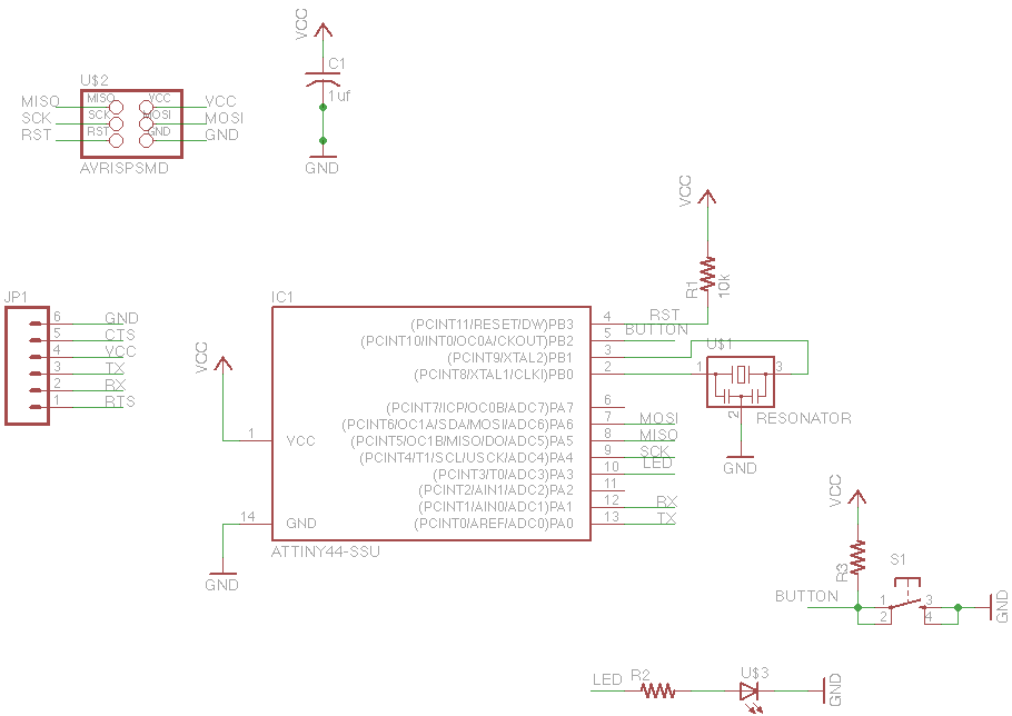
For this week's assignment, a chip design was provided, and the task was to incorporate a button and an LED (light-emitting diode). The objective was to fabricate the chip and program it to interact with the light and button. Given...

Power supplies for microcontroller based projects
This document discusses the use of small microcontrollers, such as those from the PIC and Atmel series, which typically operate at 5V and require less than 100mA for complete system functionality. Some PICs can function at lower voltages, such as...

Controlling high-current circuits
Digital output from a microcontroller is typically a low-amperage signal. For example, when a pin is set HIGH on the microcontroller (in Wiring/Arduino, it is digitalWrite(somePin, HIGH);), the voltage from that pin is usually +3.3V or +5V, with the current...