


20W bus circuit radio and megaphone
#TDA2005S
#low frequency
#power amplifier
#megaphone
#bus radio
#20W
#microphone input
#audio amplification

Description: 20W bus radio and megaphone circuit utilizing the TDA2005S double low-frequency power amplifier integrated circuit design. The front end can be connected to either a microphone input or a low-frequency radio output voltage amplification stage. Each TDA2005S provides 10W output power and can support four speakers. With two outputs, it can accommodate eight speakers, allowing for distribution in different areas of the vehicle, achieving a total output power of up to 20W.
The circuit design for the 20W bus radio and megaphone system is centered around the TDA2005S integrated circuit, which serves as a dual low-frequency power amplifier. This IC is specifically designed to drive speakers in automotive applications, providing robust performance in both radio and megaphone configurations.
The front end of the circuit can be configured to accept signals from either a microphone or a low-frequency radio source. When utilizing a microphone, the circuit amplifies the audio input, ensuring clear sound reproduction for announcements or communications. In contrast, when connected to a radio output, the circuit amplifies the audio signal to drive the speakers effectively.
Each TDA2005S amplifier stage is capable of delivering 10W of output power, making it suitable for driving multiple speakers. The design allows for the connection of up to four speakers per amplifier, with the option to use two amplifiers in parallel to support a total of eight speakers. This configuration enables sound distribution across different sections of the vehicle, enhancing the auditory experience for passengers.
The total output power of the system can reach 20W, providing sufficient volume levels for both music playback and voice announcements. The circuit may include additional components such as capacitors for coupling and decoupling, resistors for biasing, and protection diodes to safeguard against voltage spikes. Proper thermal management and power supply considerations are also essential to ensure reliable operation under varying load conditions.
Overall, the TDA2005S-based bus radio and megaphone circuit is a versatile solution for enhancing audio output in vehicles, combining functionality with ease of integration and installation.20W bus radio and megaphone circuit TDA2005S double low frequency power amplifier integrated circuit design, the front end can be connected to the microphone input or low-frequ ency radio output voltage amplification stage, each TDA200S 10W output power, can take four speakers. Two outputs with eight speakers, can be divided in different parts of the car, the total output power of up to 20W.
The circuit design for the 20W bus radio and megaphone system is centered around the TDA2005S integrated circuit, which serves as a dual low-frequency power amplifier. This IC is specifically designed to drive speakers in automotive applications, providing robust performance in both radio and megaphone configurations.
The front end of the circuit can be configured to accept signals from either a microphone or a low-frequency radio source. When utilizing a microphone, the circuit amplifies the audio input, ensuring clear sound reproduction for announcements or communications. In contrast, when connected to a radio output, the circuit amplifies the audio signal to drive the speakers effectively.
Each TDA2005S amplifier stage is capable of delivering 10W of output power, making it suitable for driving multiple speakers. The design allows for the connection of up to four speakers per amplifier, with the option to use two amplifiers in parallel to support a total of eight speakers. This configuration enables sound distribution across different sections of the vehicle, enhancing the auditory experience for passengers.
The total output power of the system can reach 20W, providing sufficient volume levels for both music playback and voice announcements. The circuit may include additional components such as capacitors for coupling and decoupling, resistors for biasing, and protection diodes to safeguard against voltage spikes. Proper thermal management and power supply considerations are also essential to ensure reliable operation under varying load conditions.
Overall, the TDA2005S-based bus radio and megaphone circuit is a versatile solution for enhancing audio output in vehicles, combining functionality with ease of integration and installation.20W bus radio and megaphone circuit TDA2005S double low frequency power amplifier integrated circuit design, the front end can be connected to the microphone input or low-frequ ency radio output voltage amplification stage, each TDA200S 10W output power, can take four speakers. Two outputs with eight speakers, can be divided in different parts of the car, the total output power of up to 20W.

Distortion In Power Amplifiers
The distortion produced by a typical solid-state Class-B power amplifier consists of eight mechanisms, all of which may coexist and whose distortion products overlap to create a complex result. Methods for isolating each mechanism for study and minimizing its contribution...

50 Watt Power Amplifier
The supply voltage should be about +/- 35 Volts at full load, which will let this little guy provide a maximum of 56 Watts (rated minimum output at 25 degrees C). To enable maximum power, it is important to get...

60W power amplifier
The TDA7294 amplifier module is a monolithic integrated circuit designed for use as an audio class AB amplifier in hi-fi applications. It has a wide voltage range and output current capability, enabling it to supply the highest power into both...

Split Power Supply Circuit for Power Amplifier
This is a simple circuit diagram for a 150W power amplifier. The circuit can be constructed without a printed circuit board (PCB). The power output ranges from 100W to 150W, depending on the power supply and the Darlington transistors used...

Power amplifier 65W with HEXFET
Cleaned Input: A medium power amplifier that is characterized by a lot of good sound quality, but simultaneously is very simple in the construction. It uses, enough time in active loudspeakers. In its output stage exist the very good FET...
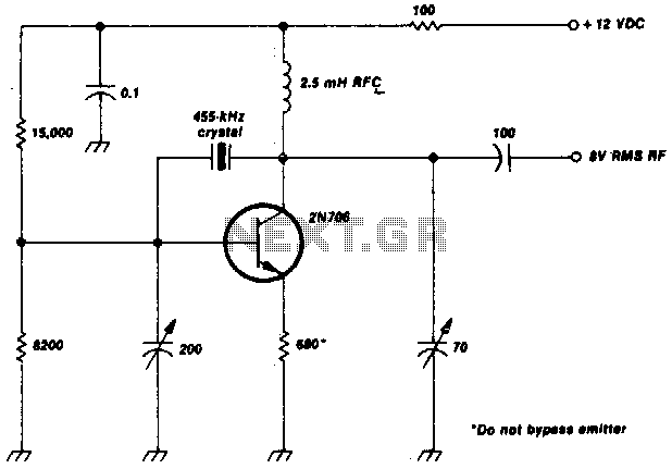
Low frequency crystal oscillator
This crystal-oscillator circuit utilizes a 455-kHz crystal. It is a straightforward project.
The crystal oscillator circuit based on a 455-kHz crystal operates by utilizing the piezoelectric properties of the crystal to generate a stable frequency. The circuit typically consists of an...

Amp Circlotron
It is a power amplifier configuration developed in the 1950s, known as a circlotron due to its original diagram being drawn in a circular shape. The best representation available is a bridge format. Its primary advantage is very low distortion....

Power amplifier circuit diamond differential input
The power supply circuits for servo systems are critical during both the adoption and operational stages.
The power supply circuit for servo systems is designed to provide stable and adequate voltage and current levels necessary for the servo motors to function...

300BSE power amplifier circuit
A request for a DIY 300BSE power amplifier schematic is made, with a specification to utilize Lowther PM6 speakers.
The 300BSE power amplifier is a well-regarded audio amplification circuit known for its warm sound and high fidelity, particularly suited for driving...