


A flash voice delay circuit

Description: The circuit includes a microphone (MIC) housed in a cylindrical body that captures sound when an object makes contact. The audio signal is coupled to an integrated circuit (IC) for amplification. The output from the IC, at pins 6 and 9, provides a trigger level for a thyristor (BCR). Once triggered, the thyristor allows current to charge a capacitor (C4) through a resistor (R4). When the voltage across C4 reaches a predetermined threshold after a specified delay, it activates a relaxation oscillator circuit, which subsequently triggers the thyristor for conduction. This action initiates a flash of light, allowing for film exposure in a photographic application. The delay time can be adjusted, and after the flash has completed, a normally closed switch (F NC) is released to turn off an LED. The circuit is designed to be ready for the next operation, with an adjustable voltage across the microphone set between 3 to 5 volts.
The described circuit functions as a sound-activated flash trigger for photographic applications. The microphone (MIC) detects sound waves generated by an object, converting them into an electrical audio signal. This signal is then routed through a coupling component to the integrated circuit (IC), which amplifies the signal to a sufficient level, specifically at the output pins 6 and 9 of the IC.
The amplified signal serves as a trigger for the thyristor (BCR), which is a semiconductor device that can switch on and off electrical currents. When the thyristor is activated, it allows current to flow through resistor R4, charging capacitor C4. The charging of C4 is crucial, as it determines the timing of the flash. The voltage across C4 will rise until it reaches a predetermined threshold, which is set to correspond with a specific delay after the initial sound detection.
Once the voltage across C4 exceeds this threshold, it triggers a relaxation oscillator circuit that further activates the thyristor, leading to the conduction phase. This phase causes the flash mechanism to operate, producing a brief but intense burst of light, which is essential for exposing photographic film. The exposure occurs while the system is in a wait state, allowing for the capture of images based on the sound-triggered event.
After the flash has been emitted, the circuit includes a normally closed switch (F NC) that, when released, turns off an LED indicator, signaling the end of the flash activity. The system is designed to be ready for subsequent operations, with an adjustable voltage across the microphone, ensuring optimal sensitivity and performance, set to operate within a range of 3 to 5 volts. This flexibility allows for the circuit to adapt to various sound levels and environmental conditions, making it suitable for diverse photographic scenarios.1C is SK - 2 integrated voice, when the object hit the sound is received in the body Xi ester cylinder MIC, the audio signal goes through a coupling obstacle to 1C. After ampli fication of the signal by the IC, the output of 6,9 feet provider level. After D- triggered thyristor BCR. Turned on, the capacitor C4 through R4 wide electricity. When C4 voltage reaches a certain value (ie n-inch seam after a given delay), single-junction pipe (BT31) the relaxation oscillator + Xu triggered thyristor BCR/conduction, so tr Wherever flash light, this time photographic hunger Bf] to open the IF in a wait state, so the film exposure. Delay time by the wind i ~ i Zan. When the flash is finished Wherever Mighty, press F NC press fS (light-emitting diode/ED off). R is ready to pick the next action as may be required to delay the hand F Off Sl closed sets. W compact fluorescent adjusted so that the voltage across the MIC for the 3- 5v.
The described circuit functions as a sound-activated flash trigger for photographic applications. The microphone (MIC) detects sound waves generated by an object, converting them into an electrical audio signal. This signal is then routed through a coupling component to the integrated circuit (IC), which amplifies the signal to a sufficient level, specifically at the output pins 6 and 9 of the IC.
The amplified signal serves as a trigger for the thyristor (BCR), which is a semiconductor device that can switch on and off electrical currents. When the thyristor is activated, it allows current to flow through resistor R4, charging capacitor C4. The charging of C4 is crucial, as it determines the timing of the flash. The voltage across C4 will rise until it reaches a predetermined threshold, which is set to correspond with a specific delay after the initial sound detection.
Once the voltage across C4 exceeds this threshold, it triggers a relaxation oscillator circuit that further activates the thyristor, leading to the conduction phase. This phase causes the flash mechanism to operate, producing a brief but intense burst of light, which is essential for exposing photographic film. The exposure occurs while the system is in a wait state, allowing for the capture of images based on the sound-triggered event.
After the flash has been emitted, the circuit includes a normally closed switch (F NC) that, when released, turns off an LED indicator, signaling the end of the flash activity. The system is designed to be ready for subsequent operations, with an adjustable voltage across the microphone, ensuring optimal sensitivity and performance, set to operate within a range of 3 to 5 volts. This flexibility allows for the circuit to adapt to various sound levels and environmental conditions, making it suitable for diverse photographic scenarios.1C is SK - 2 integrated voice, when the object hit the sound is received in the body Xi ester cylinder MIC, the audio signal goes through a coupling obstacle to 1C. After ampli fication of the signal by the IC, the output of 6,9 feet provider level. After D- triggered thyristor BCR. Turned on, the capacitor C4 through R4 wide electricity. When C4 voltage reaches a certain value (ie n-inch seam after a given delay), single-junction pipe (BT31) the relaxation oscillator + Xu triggered thyristor BCR/conduction, so tr Wherever flash light, this time photographic hunger Bf] to open the IF in a wait state, so the film exposure. Delay time by the wind i ~ i Zan. When the flash is finished Wherever Mighty, press F NC press fS (light-emitting diode/ED off). R is ready to pick the next action as may be required to delay the hand F Off Sl closed sets. W compact fluorescent adjusted so that the voltage across the MIC for the 3- 5v.

Microphone Circuit Test Oscillator
This unit would be mounted in a small plastic or preferably metal box, with a 9V battery, level control, a male XLR connector (same as on a mic) and a switch. Current drain is low, since the circuit only uses...

Simple microphone preamplifier
Cleaned Input: This is a simple microphone preamplifier circuit which you can use between your microphone and stereo amplifier. This circuit amplifier microphone suitable for use with normal home stereo amplifier line/CD/aux/tape inputs. This mic preamp can take both dynamic...
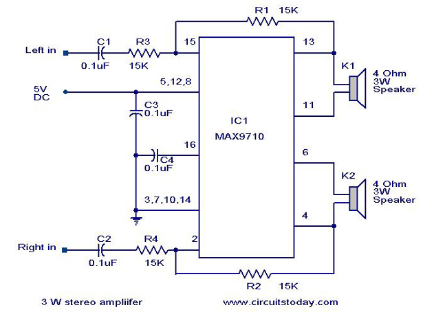
3 W Stereo amplifier using MAX 7910-Audio power amplifier circuit
An audio power amplifier circuit for a 3-watt stereo amplifier using the MAX 7910 IC is explained below.
The audio power amplifier circuit utilizing the MAX 7910 IC is designed to deliver a maximum output power of 3 watts per channel...

Bird Feeder Monitor Circuit
The first amplifier circuit is a bird phone. In this circuit, the electret microphone (MIC1) is mounted in the neck of a large plastic funnel. The amplifier, built around an MC34119, is then placed outside of the funnel with the...

Dynamic to electret microphone circuit
This is a simple microphone preamplifier circuit which you can use between your dynamic microphone and any equipment designed to work with an electret microphone (2 wire connection to electret capsule). This amplifier amplifies the low level signal to the...
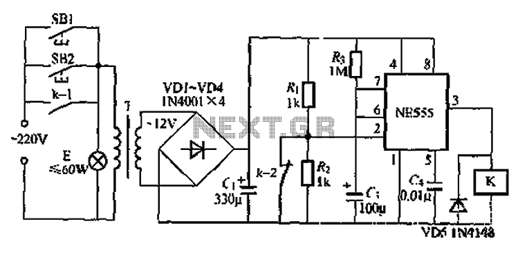
When using the lamp base circuit delay circuit 2
Another application involves the use of a NE555 delay lamp circuit, where components SB1 and SH2 act as J-light buttons that can be installed in two different locations. The lamp can be activated by pressing either SB1 or SB2, which...
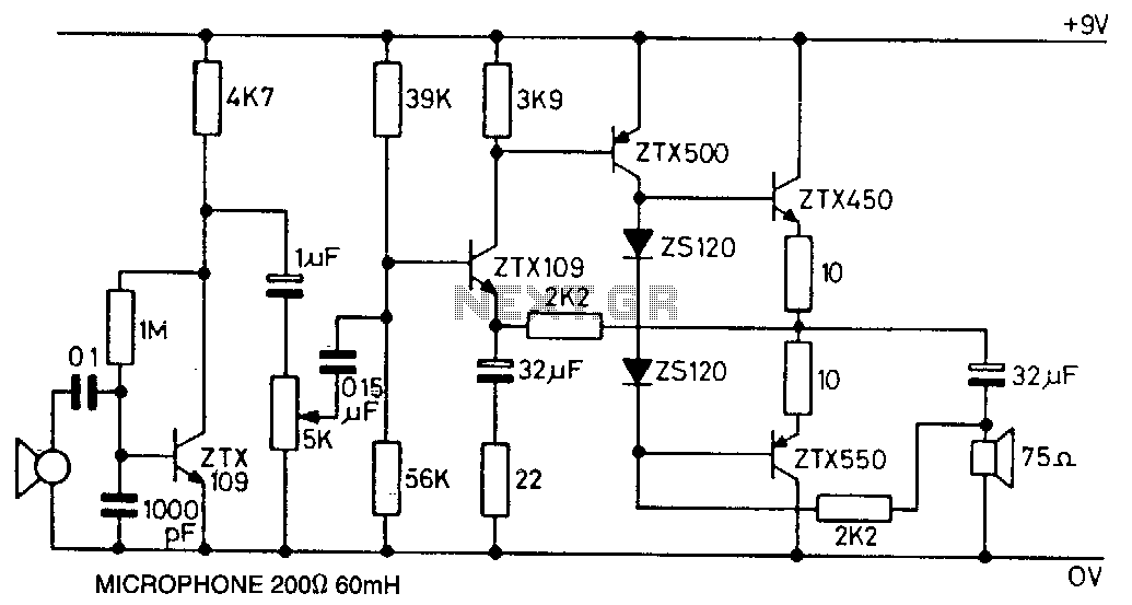
Microphone-amplifier
This circuit utilizes the ZTX450 and ZTX550 transistors configured in a push-pull output stage. The following measurements were recorded at maximum volume: Input: 0.4 mV rms, Output: 1.8 V rms, Voltage gain: 4500, Maximum output before distortion: 2.25 V rms,...

General-Purpose Output Amplifier Circuit
This general-purpose amplifier has a bandwidth of approximately 20 MHz and it uses an LM733/NE592 video amplifier integrated circuit. This circuit can be utilized as a line driver or as a LAN line driver.
The circuit employs the LM733/NE592 video amplifier...
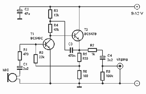
Basic Microphone preamplifier
This preamplifier amplifies the signal from a microphone, an amplifier so that it can be further strengthened. The circuit supplies an output signal line. With two transistors, it is not difficult to build such a circuit. The amplifier produces noise...