


Active Crossover
#active crossover
#audio filter
#high-pass filter
#low-pass filter
#phase correction
#signal delay
#audio engineering
#JAES
#Lipshitz-Vanderkooy
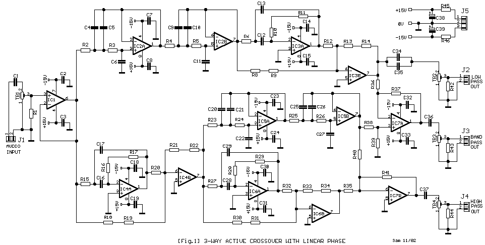
Description: The problems that exist in common crossover networks are known. The low-pass filter causes delay in the signal. On the contrary, the high-pass filter causes a pre-ahead in the signal that it goes through from this. So, the cross-frequency creates certain problems such as: 1) the signals of two filters confutation, 2) the change of phase between the filters influences axial, and 3) the axial diagram depends on the frequency. The crossover circuit attempts to resolve many of the problems reported above and is based on research by S. Lipshitz and J. Vanderkooy published in the Journal of the Audio Engineering Society. A network crossover of linear phase uses a low-pass section with the help of a time delay circuit and abstraction circuit, which gives the output signal characteristics of a low-pass filter. This delay time is not constant for the entire frequency range but is altered very slightly and primarily does not exhibit phase differences between the signals of the two outputs, even near the cross-frequency.
Part List
R1-16=100Kohms R23-24-25-26=37.5Kohms [33K+4.7K] C12-13-20-21-22=1nF 100V MKT
R2-3-4-5=56Kohms R30-31-32-33-34-35-36=10Kohms C19-23-24-30-31-32-33=47nF 100V MKT
R6-27=37.5Kohms[33K+4.7K] R37-38-39-40-41-41=10Kohms C25-26-27-28-29=1nF 100V MKT
R8-9-12-13-14=10Kohms R42-43-44=47Kohms C36-37=1uF 100V MKT
R10-28=75Kohms (150K//150K) R45-46=47 ohms C38-39=47uF 25V
R11-29=NC TR1-2-3-4=47Kohms trimmer or pot. IC1=TL071
R15=56.3Kohms C1-34-35=2.2uF 100V MKT IC2-3-4-5-6-7=TL072-NE5532
R17=12Kohms C2-3-7-8-14-15-18=47nF 100V MKT
R18-19-20-21-22=10Kohms C4-5-6-9-10-11-16-17=10nF 100V MKT All the resistors are 1/4W 1% metal film.
The crossover circuit is constituted, as it appears from the block diagram, from two low-pass filters of fourth order -24dB/oct, one for the line of low-frequency signals and one for the high frequency. In the same frequency function, there are also two delay-time units, T1 (for low cross frequency F1) and T2 (for high cross frequency F2), which provide a characteristic phase with the low-pass part. The circuit delays T1 imitate the delay time that the low-frequency filter LPF1 imports, while T2 imitates the delay time that the low-frequency filter LPF2, which exists in the line of mid frequencies, imports. The signal that emanates from the low-pass filter is processed by IC7A-B, from the signal that has suffered delay, resulting in a signal that has characteristics similar to a signal that has passed through a low-pass filter. At the exit of each line, there is a trimmer that allows for adjusting the level and balance between the loudspeakers. The circuit is powered by a stabilized voltage of +/- 15V. The use of fourth-order Linkwitz crossover networks raises the cross-frequencies to -6dB.The problems that exist in common crossover networks are known. The low-pass filter causes delay in the signal. On the contrary the high-pass filter causes be pre-ahead in the signal that it in goes through from this. So, the cross-frequency are created certain problems as 1] the signals of two filters confutation 2] the change of phase between the filters influence axial 3]to axial diagram depend from the frequency.
The crossover circuit try it unties many from the problems that report above and are based on research of S. Lipshitz and J. Vanderkooy that was published in the magazine JAES (Journal Audio Engineering Society). A network crossover of linear phase it uses a low-pass department with the help of circuit of time delay and circuit of abstraction it gives in the exit signal with characteristically low-pass filter. This delay time is not constant for entire the area of frequencies, but is altered very late and mainly doesn't exist differences of phase between the signals of two outputs, neither even near in the cross-frequency.
Part List R1-16=100Kohms R23-24-25-26=37.5Kohms [33K+4.7K] C12-13-20-21-22=1nF 100V MKT R2-3-4-5=56Kohms R30-31-32-33-34-35-36=10Kohms C19-23-24-30-31-32-33=47nF 100V MKT R6-27=37.5Kohms[33K+4.7K] R37-38-39-40-41-41=10Kohms C25-26-27-28-29=1nF 100V MKT R8-9-12-13-14=10Kohms R42-43-44=47Kohms C36-37=1uF 100V MKT R10-28=75Kohms (150K//150K) R45-46=47 ohms C38-39=47uF 25V R11-29=NC TR1-2-3-4=47Kohms trimmer or pot. IC1=TL071 R15=56.3Kohms C1-34-35=2.2uF 100V MKT IC2-3-4-5-6-7=TL072-NE5532 R17=12Kohms C2-3-7-8-14-15-18=47nF 100V MKT R18-19-20-21-22=10Kohms C4-5-6-9-10-11-16-17=10nF 100V MKT All the rsestors is 1/4W 1% metal film.
The crossover circuit is constituted as it appears from block diagram [Fig.2] from two low-pass filters of fourth order -24db/oct, one for the line of low frequency signals and one for the high frequency. In the same frequency function also the two delay-time units, T1 (for low cross frequency F1) and T2 (for high cross frequency F2) and give him of characteristically phase with the low-pass part.
The circuit delays T1 imitate the delay time that import the filter of low frequencies LPF1, while the T2 imitates the delay time that import the filter of low frequencies LPF2 that exists in the line of mid frequencies. Then the signal that emanates from low-pass filter is removed with IC7A-B, from the signal that has suffered delay, result a signal that his characteristics is same with a signal that has passed in from a low-pass filter.
In the exit of each line found a trimmer with that we can adjust the level and level between the loudspeakers. The circuit supply become from a stabilized voltage +/- 15V. The use of crossover networks of fourth-order Linkwitz heaves the cross-frequencies to find in -6db [Fig.
3].
Part List
R1-16=100Kohms R23-24-25-26=37.5Kohms [33K+4.7K] C12-13-20-21-22=1nF 100V MKT
R2-3-4-5=56Kohms R30-31-32-33-34-35-36=10Kohms C19-23-24-30-31-32-33=47nF 100V MKT
R6-27=37.5Kohms[33K+4.7K] R37-38-39-40-41-41=10Kohms C25-26-27-28-29=1nF 100V MKT
R8-9-12-13-14=10Kohms R42-43-44=47Kohms C36-37=1uF 100V MKT
R10-28=75Kohms (150K//150K) R45-46=47 ohms C38-39=47uF 25V
R11-29=NC TR1-2-3-4=47Kohms trimmer or pot. IC1=TL071
R15=56.3Kohms C1-34-35=2.2uF 100V MKT IC2-3-4-5-6-7=TL072-NE5532
R17=12Kohms C2-3-7-8-14-15-18=47nF 100V MKT
R18-19-20-21-22=10Kohms C4-5-6-9-10-11-16-17=10nF 100V MKT All the resistors are 1/4W 1% metal film.
The crossover circuit is constituted, as it appears from the block diagram, from two low-pass filters of fourth order -24dB/oct, one for the line of low-frequency signals and one for the high frequency. In the same frequency function, there are also two delay-time units, T1 (for low cross frequency F1) and T2 (for high cross frequency F2), which provide a characteristic phase with the low-pass part. The circuit delays T1 imitate the delay time that the low-frequency filter LPF1 imports, while T2 imitates the delay time that the low-frequency filter LPF2, which exists in the line of mid frequencies, imports. The signal that emanates from the low-pass filter is processed by IC7A-B, from the signal that has suffered delay, resulting in a signal that has characteristics similar to a signal that has passed through a low-pass filter. At the exit of each line, there is a trimmer that allows for adjusting the level and balance between the loudspeakers. The circuit is powered by a stabilized voltage of +/- 15V. The use of fourth-order Linkwitz crossover networks raises the cross-frequencies to -6dB.The problems that exist in common crossover networks are known. The low-pass filter causes delay in the signal. On the contrary the high-pass filter causes be pre-ahead in the signal that it in goes through from this. So, the cross-frequency are created certain problems as 1] the signals of two filters confutation 2] the change of phase between the filters influence axial 3]to axial diagram depend from the frequency.
The crossover circuit try it unties many from the problems that report above and are based on research of S. Lipshitz and J. Vanderkooy that was published in the magazine JAES (Journal Audio Engineering Society). A network crossover of linear phase it uses a low-pass department with the help of circuit of time delay and circuit of abstraction it gives in the exit signal with characteristically low-pass filter. This delay time is not constant for entire the area of frequencies, but is altered very late and mainly doesn't exist differences of phase between the signals of two outputs, neither even near in the cross-frequency.
Part List R1-16=100Kohms R23-24-25-26=37.5Kohms [33K+4.7K] C12-13-20-21-22=1nF 100V MKT R2-3-4-5=56Kohms R30-31-32-33-34-35-36=10Kohms C19-23-24-30-31-32-33=47nF 100V MKT R6-27=37.5Kohms[33K+4.7K] R37-38-39-40-41-41=10Kohms C25-26-27-28-29=1nF 100V MKT R8-9-12-13-14=10Kohms R42-43-44=47Kohms C36-37=1uF 100V MKT R10-28=75Kohms (150K//150K) R45-46=47 ohms C38-39=47uF 25V R11-29=NC TR1-2-3-4=47Kohms trimmer or pot. IC1=TL071 R15=56.3Kohms C1-34-35=2.2uF 100V MKT IC2-3-4-5-6-7=TL072-NE5532 R17=12Kohms C2-3-7-8-14-15-18=47nF 100V MKT R18-19-20-21-22=10Kohms C4-5-6-9-10-11-16-17=10nF 100V MKT All the rsestors is 1/4W 1% metal film.
The crossover circuit is constituted as it appears from block diagram [Fig.2] from two low-pass filters of fourth order -24db/oct, one for the line of low frequency signals and one for the high frequency. In the same frequency function also the two delay-time units, T1 (for low cross frequency F1) and T2 (for high cross frequency F2) and give him of characteristically phase with the low-pass part.
The circuit delays T1 imitate the delay time that import the filter of low frequencies LPF1, while the T2 imitates the delay time that import the filter of low frequencies LPF2 that exists in the line of mid frequencies. Then the signal that emanates from low-pass filter is removed with IC7A-B, from the signal that has suffered delay, result a signal that his characteristics is same with a signal that has passed in from a low-pass filter.
In the exit of each line found a trimmer with that we can adjust the level and level between the loudspeakers. The circuit supply become from a stabilized voltage +/- 15V. The use of crossover networks of fourth-order Linkwitz heaves the cross-frequencies to find in -6db [Fig.
3].

12dB-oct by the OP amplifiers low-pass filter
A 12dB/oct Butterworth filter circuit is designed to achieve a flat frequency response. The optimal value for the circuit's Q factor is 0.707, which ensures a flat characteristic. The feedback capacitance must be selected to maintain high capacity and reach...
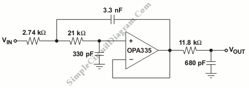
A 20-kHz Third-Order Low-Pass Filter
This is a third-order low pass filter with a corner frequency of 20 kHz, which is twice the auto-zero clock frequency.
The third-order low pass filter is designed to attenuate high-frequency signals while allowing low-frequency signals to pass through with...
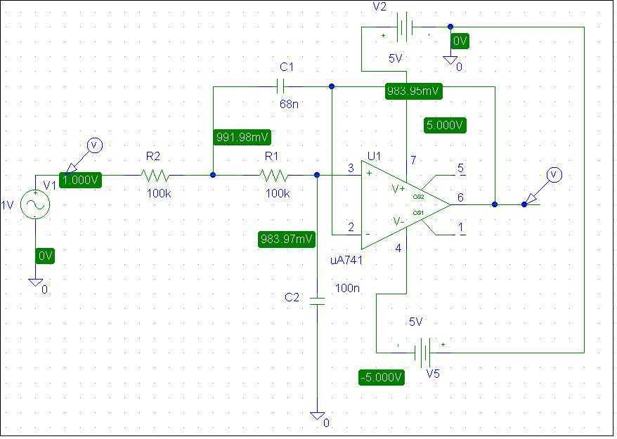
Schematic of Low-Pass Active Filter
This is a simple low pass filter that can be used at any audio circuitry. It uses the 741 opamp. More: Do not forget to use double power supply of 5 volts. You can use 2 batteries as shown in...
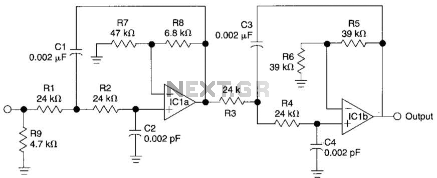
Active Fourth-Order Low-Pass Filter Circuit
This circuit is a fourth-order low-pass filter designed for operation at kilohertz frequencies. The component values for resistors R1, R2, and capacitors C1, C2, as well as resistors R3, R4 and capacitors C3, C4 can be adjusted for functionality at...

Build a Variable-Frequency Audio Band pass FilterCircuit
This variable-frequency audio bandpass filter is constructed using two 741 operational amplifiers connected in cascade. The two 741 op amps are configured as identical RC active filters and are cascaded to enhance selectivity. The filter's tuning range spans from 500...

Filter For Audio Measurements
The purpose is supposedly to account for the fact that human hearing is less sensitive at low and high frequencies than in the upper midrange, and that this variation is dependent upon the sound intensity (SPL). The Fletcher-Munson curve (as...

Audio Filter Analyzer
When this circuit is connected to a filter and an oscilloscope, the oscilloscope displays the filter's frequency response. A frequency that sweeps from low to high is applied to a filter. An oscilloscope is triggered by the start of the...

Using the same parameters more convenient level 36dB-oct low-pass filter design
A 36 dB/octave Butterworth filter consists of three sub-structures, each stage containing two filter sections. The design aims to achieve specific 3 dB frequency characteristics. The filter needs to be normalized to a value of 0 across all levels, which...

The Ultimate Audio Filter
This project extends two previous projects: the first involves adding an active filter (APF) type high-Q bandpass feature to the second receiver of the FT-2000. The second aspect is inspired by childhood memories of active filters. An active audio filter...