


ANALOG DELAY LINEECHO AND REVERB
#analog delay
#SAD 512D
#reverb
#echo
#audio processing
#shift register
#clock frequency
#signal delay
#sound effects
#Reticon

Description: This circuit utilizes an SAD 512D (Reticon) chip, which serves as a 512-stage analog shift register. By adjusting the clock frequency within the range of 5 to 50 kHz, the delay time can be configured between 51.2 ms and 5.12 ms. It is essential that the clock frequency is at least twice that of the highest audio frequency.
The SAD 512D chip is designed to function as a delay line in audio processing applications. It operates by shifting analog signals through a series of stages, allowing for the introduction of a time delay. The clock frequency controls the rate at which the signal is shifted through the stages, thereby determining the total delay experienced by the signal.
In practical applications, the circuit can be used in various audio effects, including echo and reverb. The ability to vary the clock frequency provides flexibility in adjusting the delay time to suit different audio characteristics. For instance, a lower clock frequency results in a longer delay, which can be desirable for creating pronounced echo effects, while a higher frequency yields shorter delays suitable for subtler effects.
To ensure optimal performance, the clock frequency must be carefully selected based on the audio signals being processed. The requirement for the clock frequency to be at least double the highest audio frequency is crucial to prevent aliasing and ensure that the audio signal is accurately reproduced without distortion.
Overall, the SAD 512D circuit is a versatile component in audio electronics, enabling a wide range of delay-based effects through precise control of delay time via clock frequency adjustments. Proper implementation of this circuit can enhance the auditory experience in various applications, from musical instruments to sound design in multimedia projects.This circuit uses an SAD 512D (Reticon) chip, which is a 512-stage analog shift register. By varying the clock frequency between 5 and 50 kHz, delay time can be set between 51. 2 and 5. 12 ms. The clock fre-quency must be at least twice the highest audio frequency.
The SAD 512D chip is designed to function as a delay line in audio processing applications. It operates by shifting analog signals through a series of stages, allowing for the introduction of a time delay. The clock frequency controls the rate at which the signal is shifted through the stages, thereby determining the total delay experienced by the signal.
In practical applications, the circuit can be used in various audio effects, including echo and reverb. The ability to vary the clock frequency provides flexibility in adjusting the delay time to suit different audio characteristics. For instance, a lower clock frequency results in a longer delay, which can be desirable for creating pronounced echo effects, while a higher frequency yields shorter delays suitable for subtler effects.
To ensure optimal performance, the clock frequency must be carefully selected based on the audio signals being processed. The requirement for the clock frequency to be at least double the highest audio frequency is crucial to prevent aliasing and ensure that the audio signal is accurately reproduced without distortion.
Overall, the SAD 512D circuit is a versatile component in audio electronics, enabling a wide range of delay-based effects through precise control of delay time via clock frequency adjustments. Proper implementation of this circuit can enhance the auditory experience in various applications, from musical instruments to sound design in multimedia projects.This circuit uses an SAD 512D (Reticon) chip, which is a 512-stage analog shift register. By varying the clock frequency between 5 and 50 kHz, delay time can be set between 51. 2 and 5. 12 ms. The clock fre-quency must be at least twice the highest audio frequency.

Sound-effects-generator
A variable dock-pulse generator consists of two sections of IC1, which is a 4069 CMOS hex inverter, along with resistor R1, switch S1, and capacitors C1 through C6. By adjusting R1 and switching one of the capacitors into the circuit,...

Shift register sequencer circuit
The mechanics of the Quantized Random Voltage function are intriguing. Instead of having fixed quantization steps for each output of the 4006 shift register, it is proposed to make the voltages adjustable through potentiometers. The Quantized Random Voltage function utilizes...
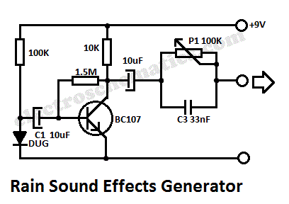
Rain Sound Effects Generator
This rain sound effects generator circuit simulates the sound of rain and can be utilized in electronic music and radio shows. The noise source employs a germanium diode that is directly polarized and subsequently amplified by a single-stage amplifier to...

Sound Effects Alarm Generator
This schematic is simple and easy to construct. The integrated circuit (IC) generates all the sound effects, with the output at Pin 3 being amplified by a transistor. A 64-ohm loudspeaker can be used instead of the 56-ohm resistor and...

Audio Beat Detect ?« Electronic Product Design
This circuit employs a digital potentiometer to enable the microcontroller to automatically adjust the circuit's gain according to the ambient audio volume. However, a standard potentiometer can be used if automatic adjustment is unnecessary. The low-pass filter design is based...

Sound Effects Generator 2
This circuit uses the Holtek HT2884 IC to produce 8 different sound effects. All sound effects are generated internally by the HT2884 IC. Power is a 3 Volt battery, but the IC will work with any voltage between 2.5 and...

Sound Effects Generator Circuit
The circuit comprises four main components: a binary counter, a digital-to-analog (D/A) converter, a voltage-controlled oscillator (VCO), and an audio output amplifier. The counting speed of the binary counter is influenced by the frequency output from the VCO, which is...

Shift register on a schematic
The circuit features a shift register chip (74HC595N), which is not available on CircuitLab. There may be a specific representation for a shift register in schematic diagrams. Although assistance with CircuitLab is not provided, schematic illustrations can be referenced on...

Echo Bender V2
A significant aspect of the soundscape effect appears to stem from adjusting the potentiometers while playing. A request has been made for a version that utilizes slide resistors instead of potentiometers, mounted on foot pedals for real-time manipulation during performance....