


audio-circuits
#hearing aid
#low cost
#cascaded amplifiers
#audio amplifier
#hearing impairment
#gain
#DIY
#sound amplification
#analog circuit
#medical

Description: This device can also be referred to as an economical hearing aid, as it can be constructed using low-cost components. Although its performance does not match that of advanced commercially available hearing aids, it can effectively assist individuals with a mild degree of hearing impairment. The design incorporates cascaded stages to enhance gain and sensitivity across most of the audible range. With a supply voltage of 3V, it is feasible to use 1/8-watt resistors, and the voltage rating for the electrolytic capacitors can be as low as 5V. This configuration allows the assembled circuit to occupy minimal space. In addition to the standard battery on/off switch (S1), a muting on/off switch (S2) is also included. Both S1 and S2 can be implemented as PCB-mounted slide switches.
The economical hearing aid circuit is designed to provide basic amplification for individuals with mild hearing loss. The main components of the circuit include a microphone, amplifying stages, and a speaker. The microphone converts sound waves into electrical signals, which are then amplified by the cascaded stages. Each stage typically consists of a transistor configured in a common-emitter or common-collector arrangement to achieve the desired gain.
The choice of a 3V power supply is crucial for the circuit's overall efficiency and compactness. Utilizing 1/8-watt resistors helps manage power consumption while maintaining performance. The low voltage rating of the electrolytic capacitors, at 5V, further contributes to the circuit's small footprint, allowing it to be easily housed in a compact enclosure.
The inclusion of the battery on/off switch (S1) is essential for conserving battery life when the device is not in use. The muting switch (S2) provides an additional layer of control, allowing users to temporarily silence the device without turning it off completely. This feature can be particularly useful in situations where the user needs to pause audio input, such as during conversations or when in a quiet environment.
The circuit's layout should be carefully designed to minimize noise and interference, ensuring that the amplified sound remains clear. Proper grounding and routing of signal paths are critical to achieving optimal performance. Additionally, consideration should be given to the placement of components to facilitate efficient assembly and maintenance.
Overall, this economical hearing aid circuit serves as a practical solution for individuals with minor hearing challenges, providing a cost-effective alternative to more sophisticated hearing devices while still delivering essential functionality.This can also be called a poor man`s hearing aid because it can be constructed from some low cost components although its performance is not comparable to that of commercially available sophisticated hearing aids, still it can serve the purpose well for persons with a low degree of hearing impairment. which have been cascaded to improve gain and s ensitivity in most audible range. With 3V supply voltage, you can afford to use 1/8-watt resistors, while the electrolytic capacitors` voltage rating can be as low as 5V. This will allow the assembled circuit to occupy very little space. Apart from the usual battery on`/off` switch S1, muting on`/off` switch S2 has also been provided. Both S1 and S2 could be PCB-mount slide switches.
The economical hearing aid circuit is designed to provide basic amplification for individuals with mild hearing loss. The main components of the circuit include a microphone, amplifying stages, and a speaker. The microphone converts sound waves into electrical signals, which are then amplified by the cascaded stages. Each stage typically consists of a transistor configured in a common-emitter or common-collector arrangement to achieve the desired gain.
The choice of a 3V power supply is crucial for the circuit's overall efficiency and compactness. Utilizing 1/8-watt resistors helps manage power consumption while maintaining performance. The low voltage rating of the electrolytic capacitors, at 5V, further contributes to the circuit's small footprint, allowing it to be easily housed in a compact enclosure.
The inclusion of the battery on/off switch (S1) is essential for conserving battery life when the device is not in use. The muting switch (S2) provides an additional layer of control, allowing users to temporarily silence the device without turning it off completely. This feature can be particularly useful in situations where the user needs to pause audio input, such as during conversations or when in a quiet environment.
The circuit's layout should be carefully designed to minimize noise and interference, ensuring that the amplified sound remains clear. Proper grounding and routing of signal paths are critical to achieving optimal performance. Additionally, consideration should be given to the placement of components to facilitate efficient assembly and maintenance.
Overall, this economical hearing aid circuit serves as a practical solution for individuals with minor hearing challenges, providing a cost-effective alternative to more sophisticated hearing devices while still delivering essential functionality.This can also be called a poor man`s hearing aid because it can be constructed from some low cost components although its performance is not comparable to that of commercially available sophisticated hearing aids, still it can serve the purpose well for persons with a low degree of hearing impairment. which have been cascaded to improve gain and s ensitivity in most audible range. With 3V supply voltage, you can afford to use 1/8-watt resistors, while the electrolytic capacitors` voltage rating can be as low as 5V. This will allow the assembled circuit to occupy very little space. Apart from the usual battery on`/off` switch S1, muting on`/off` switch S2 has also been provided. Both S1 and S2 could be PCB-mount slide switches.

audio amplifier with NE592
The broadband amplifier NE592 can be used also for building a simple selective audio amplifier. By means of the +6 V and +12 V supply voltages, a DC coupling between the product detector and the AF amplifier is possible. The...

Medical call with lighting signal receiver circuit diagram
The receiver, as depicted in the figure, assists patients in avoiding missed audio signals during the daytime. The receiver operates independently, and the lighting will automatically turn off. At night, the lighting signal receiver activates simultaneously with the patient's request....
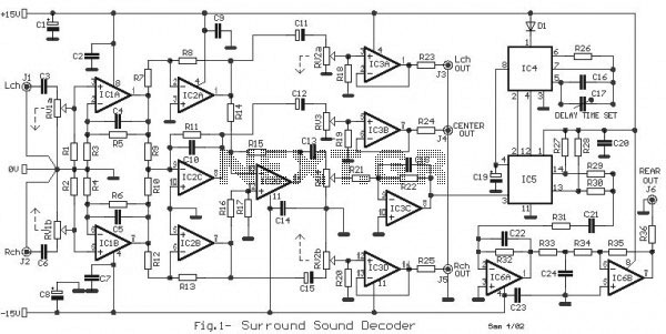
Audio Amplifier Schematic
A very high-power amplifier with 10 pairs of power transistors. It can utilize MJ15024 and MJ15025 or MJ21193 and MJ21194. These 20 transistors function as the final active components. The design is based on four integrated circuits: TL072, TL074, MN3101,...

three level audio power indicator
This circuit is designed to indicate the power output level of any audio amplifier. It is simple, portable, and displays three power levels that can be adjusted to any desired value.
The circuit operates by measuring the output voltage from the...

Schematic Audio Amplifier Circuit With NCC200 Transistor
This is a simple circuit that features high-performance power amplifiers. The power amplifier is available as a PCB, along with a complete list of components.
The described circuit utilizes high-performance power amplifiers, which are essential for applications requiring significant signal amplification....
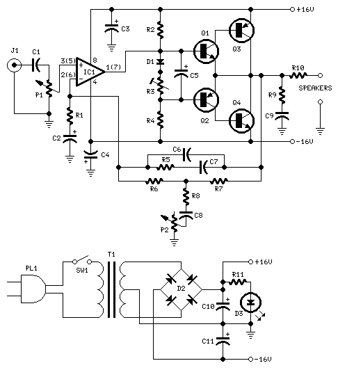
10W Audio Amplifier with Bass-boost
10W audio amplifier with bass boost. High quality, very simple design. No preamplifier required. Circuit diagram: Parts: P1 22K logarithmic potentiometer (dual-gang).
This audio amplifier circuit is designed to deliver a power output of 10 watts, making it suitable for driving...

6 Watt Hi Fi Audio Amplifier Using TDA2613
A 6-watt audio amplifier circuit utilizing the TDA2613 is presented here. The TDA2613 is an integrated Hi-Fi audio amplifier IC produced by Philips Semiconductors. The IC is designed for high-quality audio amplification.
The circuit features the TDA2613 IC, which is capable...

18 W MOSFET Amplifier Circuit With BC550C Transistor
The function of this circuit is an audio amplifier capable of delivering a decent output power with a minimal number of components, with considerable efficiency.
This audio amplifier circuit is designed to enhance audio signals, providing sufficient output power while maintaining...

Class B audio amplifier
The closer the two transistors are matched, the better the performance. It is advisable to use TIP41 and TIP42 transistors, which are closely matched NPN and PNP power transistors with a dissipation rating of 65 watts each. If a TIP41...