


bass and treble control without any ic and transistor
#bass control
#treble control
#passive circuit
#capacitors
#resistors
#potentiometer
#no IC
#no transistor
#simple circuit
#DIY audio
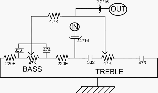
Description: This low-cost bass treble circuit consists of capacitors, resistors, and two potentiometers for bass and treble control. The circuit can be assembled without a veroboard, as the components can be soldered directly due to the simplicity of the design. It features only two-pin components, making it accessible for beginner-level hobbyists to understand and construct. However, there are some drawbacks to this circuit that should be noted. Since it does not require an external power supply, the output power is significantly lower than the input power, resulting in a decrease in volume. Additionally, the treble control does not function linearly, causing a substantial increase in treble at the extreme end of the potentiometer.
This bass treble circuit is designed to enhance audio signals by allowing users to adjust the bass and treble frequencies to their preference. The primary components include resistors and capacitors that form a passive equalizer network. The two potentiometers, designated for bass and treble control, allow for fine-tuning of the audio output. The bass control typically utilizes a low-pass filter configuration, which enables the user to boost lower frequencies, enhancing the depth and richness of the sound. Conversely, the treble control often employs a high-pass filter, which accentuates higher frequencies, contributing to clarity and brightness in the audio output.
The simplicity of the circuit is one of its key features, as it does not require complex components or extensive soldering techniques. This makes it an ideal project for beginners who are learning about audio electronics. The absence of a veroboard or PCB allows for a more hands-on approach, where hobbyists can directly engage with the components.
However, the circuit's reliance on passive components means that it may not deliver the same output power as more sophisticated active circuits that utilize operational amplifiers or dedicated power supplies. As a result, users may experience a lower volume level, which could be a limitation in certain applications. Furthermore, the non-linear behavior of the treble control may lead to an uneven response, where subtle adjustments in the potentiometer can result in significant changes in treble output, particularly at the extremes of the control range.
In summary, while this bass treble circuit offers an accessible introduction to audio electronics with its straightforward design and assembly, users should be aware of its limitations regarding output power and control linearity.This low cost bass treble circuit consists of some capacitors, resistors, and two T/C pot for BASS and TREBLE control. this circuit can be made without even a veroboard. You just solder components as this circuit network is not so complex. It has only two-pin parts. Let`s take a look at he circuit diagram. Nothing to say about it, as it is so simp le that a beginner level hobbyist can even understand and build this circuit. But there are some -ve points of this circuit which I must say, after giving you the circuit. As no external power supply, the O/P power is much lesser than I/P power, so volume decreases. The treble control doesn`t act as linear, it increases treble a lot in the end pot side
This bass treble circuit is designed to enhance audio signals by allowing users to adjust the bass and treble frequencies to their preference. The primary components include resistors and capacitors that form a passive equalizer network. The two potentiometers, designated for bass and treble control, allow for fine-tuning of the audio output. The bass control typically utilizes a low-pass filter configuration, which enables the user to boost lower frequencies, enhancing the depth and richness of the sound. Conversely, the treble control often employs a high-pass filter, which accentuates higher frequencies, contributing to clarity and brightness in the audio output.
The simplicity of the circuit is one of its key features, as it does not require complex components or extensive soldering techniques. This makes it an ideal project for beginners who are learning about audio electronics. The absence of a veroboard or PCB allows for a more hands-on approach, where hobbyists can directly engage with the components.
However, the circuit's reliance on passive components means that it may not deliver the same output power as more sophisticated active circuits that utilize operational amplifiers or dedicated power supplies. As a result, users may experience a lower volume level, which could be a limitation in certain applications. Furthermore, the non-linear behavior of the treble control may lead to an uneven response, where subtle adjustments in the potentiometer can result in significant changes in treble output, particularly at the extremes of the control range.
In summary, while this bass treble circuit offers an accessible introduction to audio electronics with its straightforward design and assembly, users should be aware of its limitations regarding output power and control linearity.This low cost bass treble circuit consists of some capacitors, resistors, and two T/C pot for BASS and TREBLE control. this circuit can be made without even a veroboard. You just solder components as this circuit network is not so complex. It has only two-pin parts. Let`s take a look at he circuit diagram. Nothing to say about it, as it is so simp le that a beginner level hobbyist can even understand and build this circuit. But there are some -ve points of this circuit which I must say, after giving you the circuit. As no external power supply, the O/P power is much lesser than I/P power, so volume decreases. The treble control doesn`t act as linear, it increases treble a lot in the end pot side

how to build inexpensive frequency
Capacitors are major electronic components classified as passive components. They are extensively used in electronic circuits, and virtually no circuit can be constructed without these essential parts. The primary function of a capacitor is to block direct current (DC) while...
Circuit Schematics
All integrated circuits (ICs) are equipped with a 0.1 µF monolithic ceramic capacitor connected across their terminals. Additionally, each board features two capacitors: a 10 µF tantalum capacitor and a 100 µF electrolytic capacitor. The START BUTTON serves as a...

Using tap potentiometer loudness circuit
Figure 1.88 illustrates the loudness control circuit utilizing multiple taps on a potentiometer. In Figure (A), the connection is made between the tap and the potentiometer's input, along with the ground. An RC compensation network is employed, where the slide...

Simple Oscillator / Pipe Locator
Occasionally, there is a requirement to create a very basic oscillator. The circuit illustrated here is remarkably straightforward, utilizing only three components.
The described oscillator circuit typically consists of a resistor, a capacitor, and a single transistor. The operation of this...

potentiometer Making an adjustable resistance
This part of the circuit is isolated from any other component, except for the 5V and ground connections. It includes LEDs and a shift register, which may not interact significantly. The LDR (Light Dependent Resistor) is utilized solely as a...

Replacing old capacitors
Original components, when still functional, exhibit stability and are not subject to infant mortality. Individual opinions may vary based on personal experiences. However, responses can differ due to several factors: the quality of the design utilizing appropriate components, the type...

muRata Manufacturing Measurement-Based SMT Capacitors
The schematic design of the equivalent circuit model for Murata Manufacturing's measurement-based GRH series SMT capacitors is derived from device measurements and modeling conducted by Murata. This model is applicable to capacitors mounted on an FR4 substrate, with constant substrate...

resistors Current flows from the source towards the sink
The circuit is designed to limit the maximum voltage between the GPIO input pin and the current source to 3.3V. This is achieved through a voltage divider configuration where the voltage across the 10K resistor is 3.3V, while the voltage...

Circuits
To prevent soldering errors, students were instructed to place all their resistors on the board first. Once their placements were verified, they could proceed with soldering. Capacitors were next, followed by LEDs and other components. The middle school class demonstrated...