


Baxandall Tone Control Circuits Using Two Transistor
#Baxandall
#tone control
#transistor
#boost and cut
#audio amplifier
#sound adjustment
#stereo
#low cost
#commercial product
#two transistor

Description: This design circuit is a tone control circuit that utilizes the popular Baxandall configuration, a straightforward circuit layout that allows for continuous boost and cut control. The circuit is inexpensive to construct and is frequently implemented in commercial products. It comprises two transistors, which can be replaced with any general audio transistors that have a current gain greater than 100, such as BC547, 2N3904, and others. The supply voltage for this circuit ranges from 9 to 15V DC. The components used are low-cost and readily available at electronics component stores.
The tone control circuit based on the Baxandall configuration is designed to enhance audio signals by providing adjustable bass and treble controls. The circuit typically includes two stages of amplification using bipolar junction transistors (BJTs), which are selected for their suitability in audio applications due to their low noise and high gain characteristics.
In the Baxandall design, the first transistor serves as the input stage, where the audio signal is fed in. The gain of this stage is adjustable via a potentiometer, allowing for fine-tuning of the input signal level. The output of the first transistor is then connected to the second transistor, which further amplifies the signal. This configuration allows for a smooth transition between boosting and cutting frequencies, providing a user-friendly interface for sound customization.
The circuit requires a DC power supply within the range of 9 to 15V, which is typical for low-power audio applications. The choice of transistors is critical; general-purpose audio transistors, such as the BC547 or 2N3904, are recommended due to their favorable characteristics for audio signal processing. These components are widely available and cost-effective, making the circuit accessible for both hobbyists and professional applications.
Passive components such as resistors and capacitors are also integral to the design. The values of these components are selected to define the frequency response of the circuit, allowing for specific adjustments to bass and treble levels. Overall, the Baxandall tone control circuit is a versatile and efficient solution for enhancing audio quality in various electronic devices.This is design circuit of tone control circuit that is use very popular Baxandall configuration, a simple circuit configuration that provides boost and cut control in continuous manner. This circuit is very cheap to build, and it`s commonly implemented in commercial product. This circuit is built by two transistors. This is the figure of the schem atic. The transistors can be substituted by any general audio transistors with small current gain more than 100 (BC547, 2N3904, and many more). The supply voltage for this circuit is 9-15V DC. The components that is used is low cost and can buy in component electronics store.
The tone control circuit based on the Baxandall configuration is designed to enhance audio signals by providing adjustable bass and treble controls. The circuit typically includes two stages of amplification using bipolar junction transistors (BJTs), which are selected for their suitability in audio applications due to their low noise and high gain characteristics.
In the Baxandall design, the first transistor serves as the input stage, where the audio signal is fed in. The gain of this stage is adjustable via a potentiometer, allowing for fine-tuning of the input signal level. The output of the first transistor is then connected to the second transistor, which further amplifies the signal. This configuration allows for a smooth transition between boosting and cutting frequencies, providing a user-friendly interface for sound customization.
The circuit requires a DC power supply within the range of 9 to 15V, which is typical for low-power audio applications. The choice of transistors is critical; general-purpose audio transistors, such as the BC547 or 2N3904, are recommended due to their favorable characteristics for audio signal processing. These components are widely available and cost-effective, making the circuit accessible for both hobbyists and professional applications.
Passive components such as resistors and capacitors are also integral to the design. The values of these components are selected to define the frequency response of the circuit, allowing for specific adjustments to bass and treble levels. Overall, the Baxandall tone control circuit is a versatile and efficient solution for enhancing audio quality in various electronic devices.This is design circuit of tone control circuit that is use very popular Baxandall configuration, a simple circuit configuration that provides boost and cut control in continuous manner. This circuit is very cheap to build, and it`s commonly implemented in commercial product. This circuit is built by two transistors. This is the figure of the schem atic. The transistors can be substituted by any general audio transistors with small current gain more than 100 (BC547, 2N3904, and many more). The supply voltage for this circuit is 9-15V DC. The components that is used is low cost and can buy in component electronics store.

Transistor Circuit Analysis
The schematic represents a relatively simple transistor circuit. Analyzing such schematics evokes memories of college days spent studying electrical engineering. However, the complexity of the schematic can be daunting after a long time away from the subject. To refresh knowledge,...

Single Transistor Half-Wave Peak Detector Circuit
Using only a single transistor and a few passive components, a fairly sensitive peak detector circuit can be built. This peak detector circuit is suitable for various applications.
The peak detector circuit utilizes a single transistor, typically configured in a common-emitter...

AC arc welding machine transistor load power path from 2
The AC arc welding machine's transistor load path for the power from the second circuit is illustrated. The figure shows a current transformer with a core cross-section of 25 mm². The transformer has a primary winding with a certain number...

pedal schematics
The 2N388A transistors are inexpensive (approximately 18 cents when purchased in lots of five or more). The 2N5088 transistors are readily available from Mouser. Other components can typically be sourced from Radio Shack or local stores. To convert to PNP...

Walkman amplifier II
The gain of the low-cost integrated circuit (IC) is internally fixed at no less than 34 dB (50 times). A unique input stage allows input signals to be referenced to ground. The output is automatically self-centering to one-half the supply...

Transistor Testers
This simple circuit is designed to test transistors in a circuit, capable of measuring down to 40 ohms across the collector-base or base-emitter junctions. It is also suitable for checking output power transistors in amplifier circuits. The operation of the...
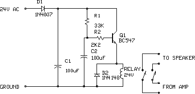
Audio Amplifier Output Relay Delay
This circuit is designed for an audio amplifier project to control the speaker output relay. Its primary function is to activate the relay that connects the speaker output to the amplifier after a delay of approximately 5 seconds following power-up,...

Simple Two-Transistor Motorcycle Alarm
When one of the switches is closed, the base of Q1 is connected to ground through D1 and R2. This activates Q1, which in turn activates Q2. Q2 connects the positive side of the relay coil to the supply line,...
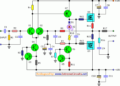
60 Watt Audio Power Amplifier
The circuit topology is similar to the previously mentioned amplifier, utilizing the robust IRFP240 and IRFP9240 MOSFET devices as the output pair, along with high-voltage Motorola transistors in the preceding stages. The supply rail voltage is conservatively set at ±40V,...