


Dynamic expansion circuit improved
#dynamic expander
#NE571
#LM1894N
#bandpass filter
#audio processing
#signal processing
#audio circuit
#dynamic range
#variable filter

Description: The NE571 and LM1894N form a dynamic expander circuit that enhances performance. This dynamic expander utilizes a variable bandpass filter with the LM1894N. It is particularly effective for dynamic expansion, requiring an RMS rectifier to mitigate noise modulation effects, often referred to as the "breathing effect." The high-quality RMS rectifier is essential for the variable bandpass filter, which precedes the LM1894N expander, effectively eliminating unwanted wheezing noise from audio signals. After processing, the noise level of the band-processed signals is managed through an NE5532N dynamic expansion amplifier. The internal operational amplifier of the NE571 has a conversion rate of 0.5V/µs and a valid passband of only a few kHz. Therefore, the NE5532N is utilized as the operational amplifier unit, replacing the original unit within the IC. The NE571 circuit primarily serves as a variable gain unit, while the NE5532N provides a comprehensive high-performance dynamic expansion circuit. Circuit adjustments can be made by varying the resistance (R4) connected to pin 5 of the NE571, with experimental results suggesting a value of 100k for optimal natural sound reproduction. The rectifying filter capacitor (C12) within the NE571 significantly influences the expander's performance, particularly regarding overshoot, rise time, and delay. It is recommended to use stable discharge tantalum electrolytic capacitors for this purpose. Additionally, the left and right audio channels, connected to pins 1 and 16, should be paralleled for balanced performance.
The NE571 and LM1894N dynamic expander circuit is designed to enhance audio signals through effective noise reduction and sound quality improvement. The NE571 serves as the core component, functioning as a variable gain amplifier that adjusts the dynamic range of the audio signal. The integration of the LM1894N bandpass filter allows for selective frequency processing, ensuring that only specific frequencies are expanded while minimizing unwanted noise.
The RMS rectifier plays a crucial role in the circuit by converting the incoming audio signal into a form that can be effectively processed by the dynamic expander. This rectification process is vital for reducing the breathing effect, which can occur in audio systems when dynamic range compression is applied. The NE5532N, known for its high performance and low distortion, is utilized to replace the internal operational amplifier of the NE571, thus enhancing the overall performance of the circuit.
The adjustment of the resistance (R4) connected to the NE571 allows for fine-tuning of the dynamic expansion ratio. A value of 100k has been determined to yield optimal results, providing a natural sound reproduction that is crucial in high-fidelity audio applications. The selection of the rectifying filter capacitor (C12) is also critical; its capacitance value and quality directly affect the expander's transient response and stability. Tantalum electrolytic capacitors are recommended due to their stability and low leakage characteristics.
In summary, this dynamic expander circuit, comprising the NE571 and LM1894N, is designed to deliver superior audio performance by effectively managing dynamic range and reducing noise artifacts. The careful selection of components and circuit configuration ensures that the system provides high-quality sound reproduction suitable for professional audio applications. Better performance is a dynamic expander circuit NE571 and LM1894N thereof. Dynamic Expander to join the Formula circuit consisting of a variable with LM1894N bandpass filter, the reason is ideal for dynamic expansion requires the use of RMS rectifier bamboo, to prevent so-called noise modulation breathing effect and RMS rectifier made into this high and can not be generally accepted by the variable band-pass filter before the expander joined by the LM18ic) 4N composition, can be eliminated - wheezing noise on the sense of hearing. After noise level band-processed signals from the N input through c9] ester consisting of 71 NE5532N dynamic expansion amplifier.
Since the conversion rate NE571 internal operational amplifier only 0.SV/pLS, and its pass band is only valid kHz t therefore Alternatively NE5532N as its operational amplifier unit, the original units shipped within the IC put the vacancy need not (see Fig. 5-11 (a o NE571 circuit only a variable gain unit and the average of these two dynamic expansion of the rectifier circuit means necessary, and the applied NE5532N form a complete, high-performance dynamic expansion of the circuit.
the circuit adjustment is achieved by spreading ratio between the NE571 5,3 feet parallel resistance R4 achieved through experiments, numerical 100k as shown, you can get a true natural sound reproduction apply if .C12 is built-NE571 rectifying the filter capacitor its value and quality of the expander overshoot, fast rise and approach of taking the amount of delay has a significant impact, should be selected with a stable discharge tantalum electrolytic capacitors. At the same time, left and right channels l, 16 feet should be parallel.
The NE571 and LM1894N dynamic expander circuit is designed to enhance audio signals through effective noise reduction and sound quality improvement. The NE571 serves as the core component, functioning as a variable gain amplifier that adjusts the dynamic range of the audio signal. The integration of the LM1894N bandpass filter allows for selective frequency processing, ensuring that only specific frequencies are expanded while minimizing unwanted noise.
The RMS rectifier plays a crucial role in the circuit by converting the incoming audio signal into a form that can be effectively processed by the dynamic expander. This rectification process is vital for reducing the breathing effect, which can occur in audio systems when dynamic range compression is applied. The NE5532N, known for its high performance and low distortion, is utilized to replace the internal operational amplifier of the NE571, thus enhancing the overall performance of the circuit.
The adjustment of the resistance (R4) connected to the NE571 allows for fine-tuning of the dynamic expansion ratio. A value of 100k has been determined to yield optimal results, providing a natural sound reproduction that is crucial in high-fidelity audio applications. The selection of the rectifying filter capacitor (C12) is also critical; its capacitance value and quality directly affect the expander's transient response and stability. Tantalum electrolytic capacitors are recommended due to their stability and low leakage characteristics.
In summary, this dynamic expander circuit, comprising the NE571 and LM1894N, is designed to deliver superior audio performance by effectively managing dynamic range and reducing noise artifacts. The careful selection of components and circuit configuration ensures that the system provides high-quality sound reproduction suitable for professional audio applications. Better performance is a dynamic expander circuit NE571 and LM1894N thereof. Dynamic Expander to join the Formula circuit consisting of a variable with LM1894N bandpass filter, the reason is ideal for dynamic expansion requires the use of RMS rectifier bamboo, to prevent so-called noise modulation breathing effect and RMS rectifier made into this high and can not be generally accepted by the variable band-pass filter before the expander joined by the LM18ic) 4N composition, can be eliminated - wheezing noise on the sense of hearing. After noise level band-processed signals from the N input through c9] ester consisting of 71 NE5532N dynamic expansion amplifier.
Since the conversion rate NE571 internal operational amplifier only 0.SV/pLS, and its pass band is only valid kHz t therefore Alternatively NE5532N as its operational amplifier unit, the original units shipped within the IC put the vacancy need not (see Fig. 5-11 (a o NE571 circuit only a variable gain unit and the average of these two dynamic expansion of the rectifier circuit means necessary, and the applied NE5532N form a complete, high-performance dynamic expansion of the circuit.
the circuit adjustment is achieved by spreading ratio between the NE571 5,3 feet parallel resistance R4 achieved through experiments, numerical 100k as shown, you can get a true natural sound reproduction apply if .C12 is built-NE571 rectifying the filter capacitor its value and quality of the expander overshoot, fast rise and approach of taking the amount of delay has a significant impact, should be selected with a stable discharge tantalum electrolytic capacitors. At the same time, left and right channels l, 16 feet should be parallel.

RAZOR SHARP CW FILTER
The circuit comprises four stages of active bandpass filtering, utilizing two A747 integrated-circuit dual operational amplifiers. It incorporates a simple threshold detector, consisting of diodes D1 and D2, positioned between stages 2 and 3 to minimize low-level background noise. Each...

Interpolating Scanner Circuit
This design is for an interpolating scanner, a circuit featuring multiple signal inputs, a control voltage input, and a signal output. The output selectively transitions between inputs, smoothly fading from one to the next as the control voltage increases. A...

Central-image-canceller
The circuit is designed to eliminate the vocal portion of an audio signal while preserving the instrumental portion. It achieves this by mixing two channels that are 180° out of phase, allowing the signals that create the center-stereo image to...

Audio Beat Detect ?« Electronic Product Design
This circuit employs a digital potentiometer to enable the microcontroller to automatically adjust the circuit's gain according to the ambient audio volume. However, a standard potentiometer can be used if automatic adjustment is unnecessary. The low-pass filter design is based...
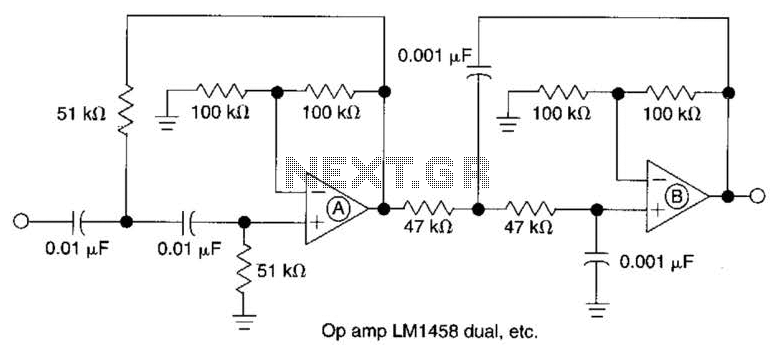
Active Second-Order Bandpass Filter Circuit
This filter circuit, which utilizes the LM1458 or a similar operational amplifier, has a frequency response ranging from 300 Hz to 3.4 kHz, exhibiting a roll-off of 12 dB per octave outside the passband. Section A serves as the high-pass...

Razor-sharp CW filter
The circuit consists of four stages of active bandpass filtering provided by two type-µ integrated-circuit dual op-amps and includes a simple threshold detector (diodes D1 and D2) between stages 2 and 3 to reduce low-level background noise. Each of the...

Voice bandpass circuit diagram
The circuit provides an 8-ohm output for connecting communication receivers and low-impedance speakers or headphones, featuring harmful interference suppression for continuous random voice transmission. The passband ranges from 55 to 2530 Hz with a 3 dB bandwidth. Inductors L1 and...

Bandpass Filter
This circuit is taken from the Progressive Communications Receiver in most of the recent ARRL Handbooks. Values for the 40 meter band are shown. If you want the ultimate in a bandpass filter for 40 or 20 meters, check out...

Variable filter
The filter generates three outputs: high-pass, bandpass, and low-pass. The frequency is linearly proportional to the gain of two integrators. Two CA3080 operational amplifiers (IC2, IC4) provide variable gain, with the resonant frequency being proportional to the current. Using 741...