


dynamic mic mid boost schematic
#dynamic mic
#mid boost
#bass rolloff
#audio enhancement
#microphone circuit
#sound processing
#audio filter
#equalization
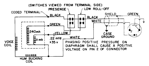
Description: Dynamic microphone mid boost and bass rolloff schematic. This schematic is derived from the documentation of a known working prototype.
The dynamic microphone mid boost and bass rolloff circuit is designed to enhance the audio signal captured by a dynamic microphone, particularly in applications where vocal clarity and presence are essential. The schematic typically includes components such as resistors, capacitors, and operational amplifiers to achieve the desired frequency response.
In this circuit, the mid boost is accomplished by utilizing a band-pass filter configuration that amplifies frequencies in the midrange, typically between 1 kHz and 3 kHz. This is crucial for ensuring that vocals are more pronounced in a mix, making them stand out during live performances or recordings. The selection of resistor and capacitor values will determine the exact frequency range that is boosted.
The bass rolloff feature is implemented to reduce lower frequencies that may muddy the mix or cause feedback issues. A high-pass filter is employed for this purpose, allowing higher frequencies to pass while attenuating those below a certain cutoff frequency. The cutoff frequency can be adjusted by changing the values of the capacitors and resistors in the circuit, allowing for customization based on the specific microphone and application.
Overall, this dynamic microphone mid boost and bass rolloff schematic serves as an effective tool for audio engineers and musicians seeking to optimize the performance of dynamic microphones in various sound environments. Proper implementation of this circuit can significantly enhance the quality of audio output, leading to clearer and more professional sound reproduction.Dynamic Mic Mid Boost And Bass Rolloff Schematic Photo: dynamic mic mid boost and bass rolloff schematic. taken from documentation of a known working po ..
The dynamic microphone mid boost and bass rolloff circuit is designed to enhance the audio signal captured by a dynamic microphone, particularly in applications where vocal clarity and presence are essential. The schematic typically includes components such as resistors, capacitors, and operational amplifiers to achieve the desired frequency response.
In this circuit, the mid boost is accomplished by utilizing a band-pass filter configuration that amplifies frequencies in the midrange, typically between 1 kHz and 3 kHz. This is crucial for ensuring that vocals are more pronounced in a mix, making them stand out during live performances or recordings. The selection of resistor and capacitor values will determine the exact frequency range that is boosted.
The bass rolloff feature is implemented to reduce lower frequencies that may muddy the mix or cause feedback issues. A high-pass filter is employed for this purpose, allowing higher frequencies to pass while attenuating those below a certain cutoff frequency. The cutoff frequency can be adjusted by changing the values of the capacitors and resistors in the circuit, allowing for customization based on the specific microphone and application.
Overall, this dynamic microphone mid boost and bass rolloff schematic serves as an effective tool for audio engineers and musicians seeking to optimize the performance of dynamic microphones in various sound environments. Proper implementation of this circuit can significantly enhance the quality of audio output, leading to clearer and more professional sound reproduction.Dynamic Mic Mid Boost And Bass Rolloff Schematic Photo: dynamic mic mid boost and bass rolloff schematic. taken from documentation of a known working po ..

Second-Order Audio Filter Performs Multiple Functions
The second-order multipurpose filter described here can function as a low-pass, bandpass, high-pass, or notch filter at audio frequencies. Its unique feature is the ability to independently vary all characteristics using potentiometers. In basic filters, only one k value is...

Filter For Audio Measurements
The purpose is supposedly to account for the fact that human hearing is less sensitive at low and high frequencies than in the upper midrange, and that this variation is dependent upon the sound intensity (SPL). The Fletcher-Munson curve (as...

The second equalization circuit
In the second equalization circuit connection method, it operates as illustrated in Figure 1-96. When the potentiometer wiper is moved to the inverting input terminal "a", the resonance impedance of the parallel combination of the feedback resistor RB reaches its...
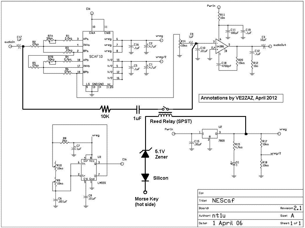
Nescaf mod
The NESCAF audio filter is a compact and cost-effective circuit that enhances amateur radio setups. It is particularly beneficial for radio receivers or transceivers that do not include an optional CW filter. However, one limitation of this filter is the...

The Ultimate Audio Filter
This project extends two previous projects: the first involves adding an active filter (APF) type high-Q bandpass feature to the second receiver of the FT-2000. The second aspect is inspired by childhood memories of active filters. An active audio filter...

Audio Filter Analyzer
When this circuit is connected to a filter and an oscilloscope, the oscilloscope displays the filter's frequency response. A frequency that sweeps from low to high is applied to a filter. An oscilloscope is triggered by the start of the...

Build a Variable-Frequency Audio Band pass FilterCircuit
This variable-frequency audio bandpass filter is constructed using two 741 operational amplifiers connected in cascade. The two 741 op amps are configured as identical RC active filters and are cascaded to enhance selectivity. The filter's tuning range spans from 500...

Audio Filters Circuits Projects
This audio noise filter circuit is a bandpass filter designed for the audio frequency range. It effectively filters out unwanted signals that fall outside the audio frequencies. The circuit consists of two filters: a low-pass filter and a high-pass filter...

Variable-Frequency Audio Bp Filter Circuit
This variable-frequency audio bandpass filter is constructed using two 741 operational amplifiers (op amps) connected in cascade. Both op amps are configured as identical RC active filters, enhancing the selectivity of the overall circuit. The filter has a tuning range...