


Electret Condenser Microphone Amplifier
#electret microphone
#amplifier
#741 op-amp
#2N2222 transistor
#condenser microphone
#audio signal
#op-amp circuit
#sound amplification

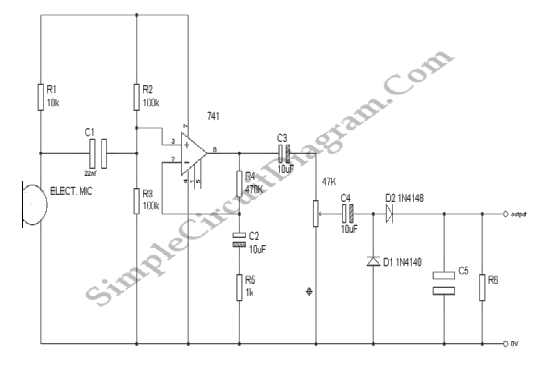
Description: Amplifier circuit for electret microphones (condenser microphones). It amplifies the audio signals picked up by the electret microphone using a 741 op-amp and a 2N2222 transistor.
The amplifier circuit designed for electret microphones utilizes a combination of a 741 operational amplifier (op-amp) and a 2N2222 transistor to enhance the weak audio signals captured by the microphone. The electret microphone, which operates on a low voltage and requires a biasing voltage, is typically connected to the non-inverting input of the op-amp.
The 741 op-amp serves as the primary amplification stage. It is configured in a non-inverting configuration to provide high input impedance, ensuring minimal loading on the microphone. The gain of the op-amp can be set using external resistors connected between the output and the inverting input. This configuration allows for precise control over the amplification factor, which is crucial for optimizing the signal level for further processing.
Following the op-amp stage, the amplified signal is fed into a 2N2222 transistor, which acts as a buffer and additional amplification stage. The transistor is configured in a common-emitter arrangement, providing further gain while offering the ability to drive larger loads. The output from the transistor stage can be connected to other audio processing components, such as filters or audio processors, ensuring that the amplified signal is suitable for various applications.
The circuit may also include additional components such as capacitors for AC coupling to eliminate DC bias and resistors for setting the operating point of the transistor. Proper power supply decoupling is essential to maintain stability and minimize noise in the circuit. Overall, this amplifier circuit effectively enhances the audio signals from electret microphones, making it suitable for applications in audio recording, communication devices, and various electronic projects.Amplifier circuit for electret microphones (condenser microphones). Amplifier the audio signals picked up by the electret microphone, using 741 op-amp and a 2N2222 transistor..
The amplifier circuit designed for electret microphones utilizes a combination of a 741 operational amplifier (op-amp) and a 2N2222 transistor to enhance the weak audio signals captured by the microphone. The electret microphone, which operates on a low voltage and requires a biasing voltage, is typically connected to the non-inverting input of the op-amp.
The 741 op-amp serves as the primary amplification stage. It is configured in a non-inverting configuration to provide high input impedance, ensuring minimal loading on the microphone. The gain of the op-amp can be set using external resistors connected between the output and the inverting input. This configuration allows for precise control over the amplification factor, which is crucial for optimizing the signal level for further processing.
Following the op-amp stage, the amplified signal is fed into a 2N2222 transistor, which acts as a buffer and additional amplification stage. The transistor is configured in a common-emitter arrangement, providing further gain while offering the ability to drive larger loads. The output from the transistor stage can be connected to other audio processing components, such as filters or audio processors, ensuring that the amplified signal is suitable for various applications.
The circuit may also include additional components such as capacitors for AC coupling to eliminate DC bias and resistors for setting the operating point of the transistor. Proper power supply decoupling is essential to maintain stability and minimize noise in the circuit. Overall, this amplifier circuit effectively enhances the audio signals from electret microphones, making it suitable for applications in audio recording, communication devices, and various electronic projects.Amplifier circuit for electret microphones (condenser microphones). Amplifier the audio signals picked up by the electret microphone, using 741 op-amp and a 2N2222 transistor..

Common intermediate frequency amplifier circuit having a circuit and on the radio
A common intermediate frequency amplifier circuit is presented, along with its components and parameters. The reference values for the components are as follows: 1) Transistors: VT1 to 3DG19, Vcc = 6V. 2) Resistance values: R1 = 50 kΩ, R2 =...

Powering Electret Microphones
A condenser microphone (electret type with two terminals) is to be powered. A resistor of 1 kΩ and a capacitor of 10 µF have been connected to its positive terminal, while the other terminal is grounded.
To power an electret condenser...

Emitter negative feedback differential amplifier gain control circuit
A controllable gain amplifier functions as an automatic gain control circuit within the execution unit. The primary methods for controlling the amplifier's gain involve two approaches: one is by adjusting certain parameters of the amplifier itself, such as emitter current,...

RECEIVER BUILDING BLOCKS
This amplifier has about 20dB of gain, bandwidth of 100MHz and noise figure of about 7dB. The output transformer is 8 turns bifilar wound on a ferrite core. Use a medium power UHF transistor 2N5109, 2N3866, 2N4427 or similar. The...
Audio Signal Strength Detector/Converter
Below is the schematic diagram of an audio input module. This module is capable of producing a DC output voltage that is proportional to the amplitude of the input signal.
The audio input module typically consists of several key components that...

audio Can I use a PNP Transistor with an Electret Microphone to get an non-inverting output for my Arduino
Read the generic sound level from an electret microphone. Several schematics utilize NPN transistors that yield an inverted output (~5V when quiet, ~0V when loud, with linear operation in between). However, a non-inverted output is desired, where a super quiet...
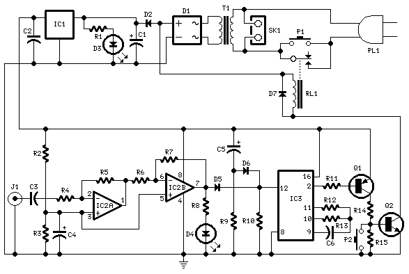
Amplifier Timer
Turns off your amplifier when idle for 15 minutes. Fed by amplifier tape-output. This circuit turns off an amplifier or any other device when a low-level audio signal fed to its input is absent for 15 minutes at least. Pushing...

liquid level sensor using 741 op amp
This liquid level sensor circuit employs a common operational amplifier IC 741 configured as a comparator. When the sensor detects that the two fluid levels (which can be represented by two small pieces of PCB or similar conductors) are not...

Simple condenser microphone mini audio amplifier circuit schematic
This circuit diagram is a simple and effective design for amplifying weak signals from a capacitive condenser microphone. It is suitable for sound sensing applications and various automatic robotic sensors. While a more complex audio amplifier circuit using the 1895...