


Electronic-tremolo
#tremolo
#audio effect
#square wave
#rc integrator
#voltage controlled resistor
#instrument
#signal modulation
#transistor

Description: The tremolo effect is created by a repeating change in volume at a frequency typically ranging from 1 to 15 Hz. A timer generates a low-frequency square wave, which is subsequently smoothed by a simple RC integrator. This varying signal modulates the input signal from the instrument. Transistor T1 functions as a voltage-controlled resistor. The output of the circuit is connected in parallel with the instrument's output. Additionally, potentiometer P1 allows for depth control by adjusting the amplitude of the modulating waveform applied to the instrument, while potentiometer P2 sets the frequency of the rate control.
The tremolo effect circuit utilizes a timer, commonly configured as an astable multivibrator, to produce a square wave output. This square wave oscillates between high and low states, which corresponds to the volume modulation. The frequency of this oscillation is adjustable via potentiometer P2, allowing users to select the desired tremolo speed within the specified range of 1 to 15 Hz.
The output from the timer feeds into an RC integrator, which serves to smooth the sharp transitions of the square wave, converting it into a more gradual wave shape. This smoothed waveform is then used to modulate the input signal from the instrument. By employing a transistor, specifically T1, as a voltage-controlled resistor, the circuit effectively controls the amplitude of the audio signal based on the modulating waveform. This configuration allows for dynamic volume changes that create the characteristic tremolo effect.
Potentiometer P1 plays a crucial role in determining the depth of the tremolo effect. By adjusting P1, the user can change the amplitude of the modulating waveform, thus affecting how pronounced the volume fluctuations are during operation. A higher setting on P1 results in a more pronounced tremolo effect, while a lower setting yields subtler modulation.
In summary, the tremolo circuit comprises a timer generating a low-frequency square wave, an RC integrator for waveform smoothing, a voltage-controlled resistor implemented with a transistor, and two potentiometers for controlling the depth and rate of the effect. This setup allows for versatile modulation of the audio signal, enhancing the overall sound texture of the instrument.The tremolo effect is generated by a repeating volume change at a rate usually between 1 and 15Hz. The timer produces a low frequency square wave that is smoothed by a simple rc integrator. This varying signal modulates the signal input from the instrument. Transistor Tl is used as a voltage controlled resistor. The output of the circuit is connected in parallel to the output of the instrument. Potentiometer P1 provides depth control by adjusting the amplitude of the modulating waveform applied to the instrument. The rate contrul frequency is set by potentiometer P2.
The tremolo effect circuit utilizes a timer, commonly configured as an astable multivibrator, to produce a square wave output. This square wave oscillates between high and low states, which corresponds to the volume modulation. The frequency of this oscillation is adjustable via potentiometer P2, allowing users to select the desired tremolo speed within the specified range of 1 to 15 Hz.
The output from the timer feeds into an RC integrator, which serves to smooth the sharp transitions of the square wave, converting it into a more gradual wave shape. This smoothed waveform is then used to modulate the input signal from the instrument. By employing a transistor, specifically T1, as a voltage-controlled resistor, the circuit effectively controls the amplitude of the audio signal based on the modulating waveform. This configuration allows for dynamic volume changes that create the characteristic tremolo effect.
Potentiometer P1 plays a crucial role in determining the depth of the tremolo effect. By adjusting P1, the user can change the amplitude of the modulating waveform, thus affecting how pronounced the volume fluctuations are during operation. A higher setting on P1 results in a more pronounced tremolo effect, while a lower setting yields subtler modulation.
In summary, the tremolo circuit comprises a timer generating a low-frequency square wave, an RC integrator for waveform smoothing, a voltage-controlled resistor implemented with a transistor, and two potentiometers for controlling the depth and rate of the effect. This setup allows for versatile modulation of the audio signal, enhancing the overall sound texture of the instrument.The tremolo effect is generated by a repeating volume change at a rate usually between 1 and 15Hz. The timer produces a low frequency square wave that is smoothed by a simple rc integrator. This varying signal modulates the signal input from the instrument. Transistor Tl is used as a voltage controlled resistor. The output of the circuit is connected in parallel to the output of the instrument. Potentiometer P1 provides depth control by adjusting the amplitude of the modulating waveform applied to the instrument. The rate contrul frequency is set by potentiometer P2.

pedal schematics
The 2N388A transistors are inexpensive (approximately 18 cents when purchased in lots of five or more). The 2N5088 transistors are readily available from Mouser. Other components can typically be sourced from Radio Shack or local stores. To convert to PNP...

One transistor audio mixer (2N3563)
This circuit mixer features internal amplification using a 2N3563 transistor. Two input signals can be independently adjusted via VRI and VR2. The VR3 balance control allows for the attenuation of one signal while the other remains active. Additionally, the transistor...
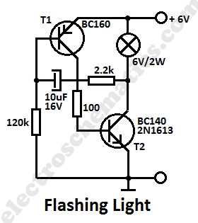
Flashing Light Circuit with Transistors
This simple flashing light circuit operates at 6 volts and 0.5A, exhibiting low current consumption when the light bulb is turned off. The frequency of the flashing is predetermined.
The circuit consists of a power supply, typically a battery or a...
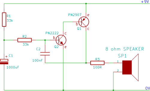
rising pitch siren
A two-transistor electronic siren breadboard circuit that produces an audible rising pitch on a loudspeaker. This circuit serves as a tutorial for beginners in electronics.
The two-transistor siren circuit operates by utilizing the properties of transistors to create an oscillating signal...

Basic reference bias circuit transistor - negative voltage feedback
Basic reference bias circuit using a transistor with negative voltage feedback.
The basic reference bias circuit utilizing a transistor with negative voltage feedback is designed to provide a stable output voltage or current that is largely independent of variations in temperature...

Transistor inverter circuit 6
This is a transistor inverter circuit diagram rated for 100 watts, designed as an easy-to-build circuit. It utilizes only transistors and does not incorporate any integrated circuits. The circuit converts a 12V battery input to a 220V, 50Hz square wave...

Transistor common emitter amplifier circuit
The circuit is a bias circuit for automatic stabilizers that maintains a stable quiescent operating point with good thermal stability. It utilizes a three-pole tube with an NPN type transistor, characterized by a small Iceo. An adjustment potentiometer, RP, is...

MAGNETOSTRICTION TV REMOTE CONTROL
The frequency of a transistor oscillator is regulated by two different lengths of nickel tubing, each containing two coil windings. One coil functions as a driver, while the other serves as a pickup to generate feedback voltage necessary for maintaining...

The Transistor Amplifier-P2
The three circuits described provide a constant current to the LED (or LEDs) when the supply voltage reaches 15V or higher. The second and third circuits can be activated or deactivated through the input line by turning on the top...