


Five uses tri-state logic audio pen CD4066 555
#tri-state logic
#CD4066
#555 timer
#multivibrator
#RC circuit
#audio circuit
#switch
#signal processing
#electronic pen
#sound generation

Description: The circuit, illustrated in Figure five, employs a tri-state logic pen audio circuit. It primarily consists of a multivibrator, a four-way switch (CD4066, IC1), and several RC components. The multivibrator (555, IC2), along with resistors R7, R8, R9 and capacitor C1, is responsible for generating the oscillation frequency that controls IC1's three states.
The circuit utilizes a 555 timer configured in astable mode, which generates a continuous square wave output. This output is used to control the four-way switch (CD4066), allowing for the selection between different audio signals or pathways. The CD4066 is a quad bilateral switch that can connect or disconnect four independent signal paths, providing flexibility in routing audio signals based on the state of the multivibrator.
Resistors R7, R8, and R9, in conjunction with capacitor C1, determine the frequency and duty cycle of the oscillation produced by the 555 timer. The values of these components can be adjusted to set the desired operating frequency of the multivibrator, which directly influences the switching rate of the CD4066.
This tri-state logic pen audio circuit is particularly useful in applications requiring dynamic audio signal routing, such as in mixers or effects processors, where multiple audio sources need to be switched seamlessly. The integration of the multivibrator and the CD4066 allows for efficient control of audio pathways, enabling complex audio manipulation without the need for mechanical switches, thereby enhancing reliability and reducing wear over time.As shown in Figure five uses tri-state logic pen audio circuit. The circuit mainly by the multivibrator, four-way switch CD4066 (IC1) circuit with some RC com ponents consisting of other components. Wherein the multivibrator 555 (IC2) and R7, R8, R9, C1 constituted by the oscillation frequency off IC1-3 state control.
The circuit utilizes a 555 timer configured in astable mode, which generates a continuous square wave output. This output is used to control the four-way switch (CD4066), allowing for the selection between different audio signals or pathways. The CD4066 is a quad bilateral switch that can connect or disconnect four independent signal paths, providing flexibility in routing audio signals based on the state of the multivibrator.
Resistors R7, R8, and R9, in conjunction with capacitor C1, determine the frequency and duty cycle of the oscillation produced by the 555 timer. The values of these components can be adjusted to set the desired operating frequency of the multivibrator, which directly influences the switching rate of the CD4066.
This tri-state logic pen audio circuit is particularly useful in applications requiring dynamic audio signal routing, such as in mixers or effects processors, where multiple audio sources need to be switched seamlessly. The integration of the multivibrator and the CD4066 allows for efficient control of audio pathways, enabling complex audio manipulation without the need for mechanical switches, thereby enhancing reliability and reducing wear over time.As shown in Figure five uses tri-state logic pen audio circuit. The circuit mainly by the multivibrator, four-way switch CD4066 (IC1) circuit with some RC com ponents consisting of other components. Wherein the multivibrator 555 (IC2) and R7, R8, R9, C1 constituted by the oscillation frequency off IC1-3 state control.

2 Way Switch Wire Electrical
The following circuit illustrates a 2-way switch wiring electrical circuit diagram. Features include the ability to turn on the lights using switch S1, which has three terminals.
The 2-way switch circuit is commonly used in residential and commercial applications to control...

Positive Trigger Timer Circuit
This 555 timer is designed uniquely to provide a positive output through control over its reset pin. Typically, the 555 timer IC is triggered by applying a negative voltage.
The 555 timer is a versatile integrated circuit widely used in various...

Electronics Grasshopper using 555
This project is designed for children and electronics beginners. It replicates the sound of a grasshopper or cockroach, producing a shrill noise at night. The circuit, referred to as the Electronics Grasshopper, generates a PI-PI sound and can function as...
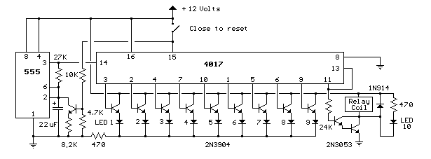
9 Second LED Timer and Relay
This circuit provides a visual 9-second delay using 10 LEDs before closing a 12-volt relay. When the reset switch is closed, the 4017 decade counter resets to the 0 count, illuminating the LED driven from pin 3. The 555 timer...

Knight Rider Lights
The 555 timer IC is connected for Astable Operation, the clock pulses are fed to the 4017 IC via the 10K resistor. The 4017 is a 10 stage counter, each of the outputs is connected to the appropriate LED, as...

555 timer Electronic roulette wheel circuit and explanation
This electronic circuit is a simplified version of an electronic roulette game, utilizing the 4017 integrated circuit (IC), which functions as a 10-stage decade counter/divider. It is driven by a versatile 555 IC configured as a voltage-controlled oscillator (VCO). The...

relay flasher circuit
In this circuit, the 555 Timer IC is configured as an astable multivibrator, and a 12-volt relay is operated through pin 3 of the IC. The IC generates continuous pulses at pin 3, which activate and deactivate the relay, causing...

Water Activated Alarm
The circuit uses a 555 timer wired as an astable oscillator and powered by the emitter current of the BC109C. Under dry conditions, the transistor will have no bias current and be fully off. As the probes get wet, a...

Basic Multivibrator
When this circuit is activated, the inherent offset of the devices acts as an automatic starting voltage. The output voltage V0 becomes positive, and the positive feedback through R2 and R1 drives the output to saturation. The elevated voltage at...