


GOL tremelo project
#tremolo
#guitar pedal
#optical coupling
#audio effect
#DIY
#music
#electronics
#sound modulation
#vintage
#circuit design

Description: This project is an excellent choice for anyone interested in creating a traditional tremolo pedal that utilizes the original optical coupling technology found in devices like the Reslytone RT-18. While many tremolo circuits are available online, many either do not function properly or do not perform well. After experimenting with numerous circuits, a simplified version of the Reslytone RT-18 was developed. Although the initial circuit worked, it depended on various combinations of resistors and capacitors to produce a smooth waveform from an astable vibrator circuit, which was difficult to interpret from the schematic. After considerable effort, a successful new circuit was completed that operates on standard 9V DC and avoids undesirable pumping by using an LED coupled to a light-dependent resistor (LDR) for variable volume control, akin to the Reslytone RT-18. The repeat rate ranges from 1.5 to 15 times per second, with fully variable intensity from zero to nearly full cut-off. The oscillator is an op-amp Wein Bridge oscillator that drives the LED/LDR through a Darlington transistor configuration. The guitar signal is processed through a simple transistor/FET coupling circuit. The op-amp provides pulsing to the LED and also powers an indicator LED on the unit, displaying both frequency and intensity of the tremolo effect. This project is ideal for technically inclined musicians and is cost-effective. It includes a true bypass stomp switch. A vero board layout has been designed for this circuit. Although there are many affordable and effective tremolo pedals on the market, such as the Boss PN-2, there are concerns regarding sound quality, particularly the lack of true bypass and the undesirable tonal changes when engaged. This project aims to address these issues, emphasizing the preference for pure sound quality over convenience. Many commercially available pedals utilize standard op-amps, which are less desirable in audiophile contexts. This raises questions about the attention paid to sound quality by modern designers, especially in an era dominated by digital music formats.
The tremolo pedal circuit employs optical coupling technology to achieve a smooth modulation effect that is both versatile and high-quality. The core of the design is the Wein Bridge oscillator, which is known for its ability to produce low-distortion sine waves. This oscillator generates the control signal for the LED, which in turn modulates the light intensity received by the LDR. The LDR's resistance changes in response to the LED's brightness, effectively controlling the audio signal's amplitude and creating the characteristic tremolo effect.
The use of a Darlington transistor configuration enhances the circuit's ability to drive the LED efficiently while providing the necessary current gain. This arrangement ensures that the LED operates within its optimal range, producing a consistent light output that directly influences the LDR's performance. The inclusion of a simple transistor/FET coupling circuit allows for minimal signal degradation, preserving the integrity of the guitar's tone as it passes through the pedal.
The pedal's user interface includes a true bypass switch, which allows players to seamlessly integrate the pedal into their signal chain without altering the sound when the effect is not engaged. The indicator LED provides visual feedback on the current frequency and intensity settings, allowing users to make real-time adjustments during performance.
The circuit's design considers the common pitfalls associated with standard op-amps, such as crossover distortion, which can negatively affect audio fidelity. By utilizing discrete components and a class A single-ended configuration, this tremolo pedal aims to deliver superior sound quality, reminiscent of vintage designs like the Reslytone RT-18.
Overall, this tremolo pedal project represents a thoughtful approach to combining traditional techniques with modern requirements, catering to musicians who prioritize sound quality in their effects. The design not only meets practical needs but also reflects a commitment to preserving the richness of the guitar's tone in live performance settings.This is a really good project for anyone wanting a good old fashioned tremelo pedal using the original optical coupling technology employed in such things as the Reslytone RT-18. I reckon it`s pretty unique with what`s around. There are any number of tremelo circuits on the net, but a lot them either don`t work at all or not that well.
I tried nu merous circuits and then tried to effect a simplified version of the Reslytone RT-18. Although I got it working, I found that it relies on a number of combinations of resistors and capacitors switched in banks to give the very smooth waveform it generates from the astable vibrator circuit. I cannot decipher the part of the schematic that does this. It`s just too ambiguous. After spending quite some time, I have a winner! The new circuit just completed works perfectly, runs on standard 9V DC, and produces no undesirable pumping because it uses an LED coupled to an LDR (light dependent resistor) to act as the variable volume control, just like the Reslytone RT-18.
The repeat rate goes from 1. 5 times a second to about 15 times a second, and has a fully variable intensity from zero to almost a full cut-off. The oscillator is an op-amp Wein Bridge oscillator driving the LED / LDR via a Darlington transistor configuration.
The signal from the guitar only passes through a simple transistor / FET coupling circuit. The op-amp just supplies pulsing to the LED, and also supplies the indicator LED on the top of the unit showing both the frequency & intensity of the tremelo. It`s a great little project for the tech inclined player, and cheap to make. It employs a true bypass stomp switch of course. I have designed the vero board layout which can be viewed here. I realise that there are any number of affordable whiz bang tremelos on the market which work perfectly.
I have one - a Boss PN-2 (see left). My complaint is that it has no true bypass and when in straight mode, it changes the sound too much - makes it brittle. Things such as this sound great in the lounge room or music shop, but disappoint at a real gig. After a while you become aware that the guitar doesn`t sound as rich as with it out of the setup. This ain`t good enough for me. I`m a purest. Most of these devices use bog-standard op-amps to handle the audio signal which are a no-no in audiophile circles.
For this reason I am thinking of turfing the occasionally used BOSS DD-2 out of my setup, or making a true bypass past it because I have noticed it dulls the sound compared to going straight into the amp. Simple class `A` `single ended` circuits using discreet transistors sound better than cheap op-amps, which are really class `B` push-pull circuits.
A push-pull circuit is most often characterised by bad harmonic characteristics due to the crossover distortion between the +ve & -ve halves of the circuit. The Shin-ei Reslytone RT-18 is a good example of an old circuit sounding better than contemporary ones.
Really good op-amps cost a lot compared to the average two bob one, and FX manufacturers don`t use the good ones in their pedals these days. I wonder sometimes whether designers actually listen to stuff any more. With the proliferation of mp3 and i-pods etc. I don`t think folks are generally attuned to the subtleties.
The tremolo pedal circuit employs optical coupling technology to achieve a smooth modulation effect that is both versatile and high-quality. The core of the design is the Wein Bridge oscillator, which is known for its ability to produce low-distortion sine waves. This oscillator generates the control signal for the LED, which in turn modulates the light intensity received by the LDR. The LDR's resistance changes in response to the LED's brightness, effectively controlling the audio signal's amplitude and creating the characteristic tremolo effect.
The use of a Darlington transistor configuration enhances the circuit's ability to drive the LED efficiently while providing the necessary current gain. This arrangement ensures that the LED operates within its optimal range, producing a consistent light output that directly influences the LDR's performance. The inclusion of a simple transistor/FET coupling circuit allows for minimal signal degradation, preserving the integrity of the guitar's tone as it passes through the pedal.
The pedal's user interface includes a true bypass switch, which allows players to seamlessly integrate the pedal into their signal chain without altering the sound when the effect is not engaged. The indicator LED provides visual feedback on the current frequency and intensity settings, allowing users to make real-time adjustments during performance.
The circuit's design considers the common pitfalls associated with standard op-amps, such as crossover distortion, which can negatively affect audio fidelity. By utilizing discrete components and a class A single-ended configuration, this tremolo pedal aims to deliver superior sound quality, reminiscent of vintage designs like the Reslytone RT-18.
Overall, this tremolo pedal project represents a thoughtful approach to combining traditional techniques with modern requirements, catering to musicians who prioritize sound quality in their effects. The design not only meets practical needs but also reflects a commitment to preserving the richness of the guitar's tone in live performance settings.This is a really good project for anyone wanting a good old fashioned tremelo pedal using the original optical coupling technology employed in such things as the Reslytone RT-18. I reckon it`s pretty unique with what`s around. There are any number of tremelo circuits on the net, but a lot them either don`t work at all or not that well.
I tried nu merous circuits and then tried to effect a simplified version of the Reslytone RT-18. Although I got it working, I found that it relies on a number of combinations of resistors and capacitors switched in banks to give the very smooth waveform it generates from the astable vibrator circuit. I cannot decipher the part of the schematic that does this. It`s just too ambiguous. After spending quite some time, I have a winner! The new circuit just completed works perfectly, runs on standard 9V DC, and produces no undesirable pumping because it uses an LED coupled to an LDR (light dependent resistor) to act as the variable volume control, just like the Reslytone RT-18.
The repeat rate goes from 1. 5 times a second to about 15 times a second, and has a fully variable intensity from zero to almost a full cut-off. The oscillator is an op-amp Wein Bridge oscillator driving the LED / LDR via a Darlington transistor configuration.
The signal from the guitar only passes through a simple transistor / FET coupling circuit. The op-amp just supplies pulsing to the LED, and also supplies the indicator LED on the top of the unit showing both the frequency & intensity of the tremelo. It`s a great little project for the tech inclined player, and cheap to make. It employs a true bypass stomp switch of course. I have designed the vero board layout which can be viewed here. I realise that there are any number of affordable whiz bang tremelos on the market which work perfectly.
I have one - a Boss PN-2 (see left). My complaint is that it has no true bypass and when in straight mode, it changes the sound too much - makes it brittle. Things such as this sound great in the lounge room or music shop, but disappoint at a real gig. After a while you become aware that the guitar doesn`t sound as rich as with it out of the setup. This ain`t good enough for me. I`m a purest. Most of these devices use bog-standard op-amps to handle the audio signal which are a no-no in audiophile circles.
For this reason I am thinking of turfing the occasionally used BOSS DD-2 out of my setup, or making a true bypass past it because I have noticed it dulls the sound compared to going straight into the amp. Simple class `A` `single ended` circuits using discreet transistors sound better than cheap op-amps, which are really class `B` push-pull circuits.
A push-pull circuit is most often characterised by bad harmonic characteristics due to the crossover distortion between the +ve & -ve halves of the circuit. The Shin-ei Reslytone RT-18 is a good example of an old circuit sounding better than contemporary ones.
Really good op-amps cost a lot compared to the average two bob one, and FX manufacturers don`t use the good ones in their pedals these days. I wonder sometimes whether designers actually listen to stuff any more. With the proliferation of mp3 and i-pods etc. I don`t think folks are generally attuned to the subtleties.
Glue stck torch
This project, developed around 2005, involves constructing a torch using a glue stick, which conveniently accommodates an AA battery within its plastic casing. To create a functional battery holder, contacts for both the positive and negative connections are necessary. The...

Tremolo Effect Circuit for Electric Guitar or Other Musical Instruments
A tremolo circuit is a type of sound effect commonly utilized in guitar effect pedals. This effect is achieved by modulating the amplitude of an audio signal. The shape of the modulating signal can vary and may include square wave,...
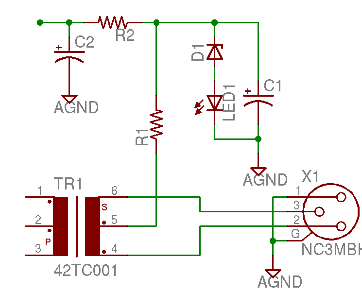
Help with a schematic please
A project is underway to construct the CountryHick DI as illustrated on DIYFactory, incorporating a few minor modifications. The final design aims to be a 1U unit with four inputs.
The CountryHick DI (Direct Injection) box is a crucial tool in...

Tremolo
This simple circuit can color the sound coming from your audio system. Clocking for the circuit is provided by an oscillator built from one quarter of a 4093 quad NAND Schmitt trigger. With the component values shown, it will run...

Sound-modulated light source
This circuit modulates a light beam using audio signals from an amplifier's output. By adjusting the 10 K potentiometer to a value slightly less than the Vbe of the transistor, the circuit operates as a peak detector. This configuration drives...

MePADS
If you are considering building the Desert Ratt 2, it is advisable to read all the accompanying text, as it contains relevant construction details. Engaging with the comments and replies can also provide additional insights, as previous blog posts have...
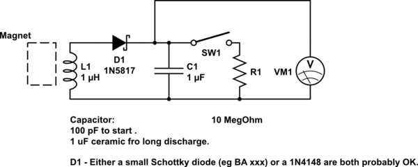
DIY kinetic energy harvester
A DIY kinetic energy harvester utilizing the electromagnetic method to generate electricity. The materials that will be used are currently known.
The project involves creating a kinetic energy harvester that converts mechanical energy from motion into electrical energy through electromagnetic induction....

Boss GE-7 Equalizer guitar pedal schematic diagram
The Boss GE-7 Equalizer pedal modifies the harmonic content of an instrument across 7 distinct frequency bands, spanning from 100Hz to 6.4kHz, with a boost or cut of up to 15dB for each band. An additional Level control knob allows...

Buffer Issues
Currently, there is a prototype of a guitar pedal in development. There are issues with the input buffer, and assistance is needed to address these problems.
The input buffer in a guitar pedal is a critical component that serves to isolate...