


Guitar Reverb Pedal project

Description: This circuit was inspired by a friend who wanted a reverb for his portable guitar amplifier. I originally tried using NE5532 low noise op-amps for the buffer stages but they were too noisy for the low level circuits so I switched to discrete 2N3904 transistors, they seem to be fairly quiet. This circuit has a nice feature not found in most reverbs, a drive control for the spring amp. The drive can be turned way up and a nice smooth distortion effect will come out of the spring. The circuit will run on a 9V battery but will probably run it down fairly quickly, it draws about 30mA idle and around 100mA with a full signal going through. Be sure to measure the DC voltage from the wall wart, they seldom agree with the label and vary a lot with load current. The circuit should work ok up to 15VDC. I built the prototype circuit right into the reverb spring box for minimal size.
The described circuit is a portable reverb unit designed for use with a guitar amplifier, utilizing discrete 2N3904 transistors for signal amplification. The choice of transistors over operational amplifiers (such as the NE5532) is significant; while op-amps are generally favored for their low noise characteristics, in this instance, the discrete transistors provide a quieter operation suitable for low-level audio signals.
The circuit features a drive control that allows the user to adjust the input signal to the spring reverb unit. This control can be set to higher levels, producing a smooth distortion effect, which is a desirable characteristic in electric guitar applications. The ability to manipulate the drive level enhances the versatility of the reverb effect, catering to various musical styles and preferences.
Powering the circuit with a 9V battery is practical, but it is important to note that the current consumption is approximately 30mA at idle and can peak at around 100mA when the signal is fully driven. This high current draw indicates that while the circuit can operate on battery power, it may deplete the battery relatively quickly, especially during extended use.
For optimal performance, it is recommended to measure the DC output voltage from any external power supply, such as a wall wart, as the actual voltage can vary based on load conditions. The circuit is designed to operate effectively within a voltage range of up to 15VDC, providing flexibility in power supply options.
The compact design of the prototype, integrated directly into the reverb spring box, highlights an emphasis on minimizing space while maintaining functionality. This approach not only conserves physical space but also likely enhances the overall aesthetic and portability of the amplifier setup.
In summary, the circuit combines practical design with functional versatility, making it an appealing choice for musicians seeking a portable reverb solution that can deliver quality sound effects.This circuit was inspired by a friend who wanted a reberb for his portable guitar amplifier. I originally tried using NE5532 low noise op-amps for the buffer stages but they were too noisy for the low level circuits so I switched to discrete 2N3904 transistors, they seem to be fairly quiet. This circuit has a nice feature not found in most reverbs, a drive control for the spring amp. The drive can be turned way up and a nice smooth distortion effect will come out of the spring. The circuit will run on a 9V battery but will probably run it down fairly quickly, it draws about 30ma idle and around 100ma with a full signal going through.
Be sure to measure the DC voltage from the wall wart, they seldom agree with the label and vary a lot with load current. The circuit should work ok up to 15VDC. I built the prototype circuit right into the reverb spring box for minimal size, it is a
The described circuit is a portable reverb unit designed for use with a guitar amplifier, utilizing discrete 2N3904 transistors for signal amplification. The choice of transistors over operational amplifiers (such as the NE5532) is significant; while op-amps are generally favored for their low noise characteristics, in this instance, the discrete transistors provide a quieter operation suitable for low-level audio signals.
The circuit features a drive control that allows the user to adjust the input signal to the spring reverb unit. This control can be set to higher levels, producing a smooth distortion effect, which is a desirable characteristic in electric guitar applications. The ability to manipulate the drive level enhances the versatility of the reverb effect, catering to various musical styles and preferences.
Powering the circuit with a 9V battery is practical, but it is important to note that the current consumption is approximately 30mA at idle and can peak at around 100mA when the signal is fully driven. This high current draw indicates that while the circuit can operate on battery power, it may deplete the battery relatively quickly, especially during extended use.
For optimal performance, it is recommended to measure the DC output voltage from any external power supply, such as a wall wart, as the actual voltage can vary based on load conditions. The circuit is designed to operate effectively within a voltage range of up to 15VDC, providing flexibility in power supply options.
The compact design of the prototype, integrated directly into the reverb spring box, highlights an emphasis on minimizing space while maintaining functionality. This approach not only conserves physical space but also likely enhances the overall aesthetic and portability of the amplifier setup.
In summary, the circuit combines practical design with functional versatility, making it an appealing choice for musicians seeking a portable reverb solution that can deliver quality sound effects.This circuit was inspired by a friend who wanted a reberb for his portable guitar amplifier. I originally tried using NE5532 low noise op-amps for the buffer stages but they were too noisy for the low level circuits so I switched to discrete 2N3904 transistors, they seem to be fairly quiet. This circuit has a nice feature not found in most reverbs, a drive control for the spring amp. The drive can be turned way up and a nice smooth distortion effect will come out of the spring. The circuit will run on a 9V battery but will probably run it down fairly quickly, it draws about 30ma idle and around 100ma with a full signal going through.
Be sure to measure the DC voltage from the wall wart, they seldom agree with the label and vary a lot with load current. The circuit should work ok up to 15VDC. I built the prototype circuit right into the reverb spring box for minimal size, it is a

Compound Op Amp Vco Driver
This circuit produces a 5 to 25 V output to drive a voltage-controlled oscillator (VCO) from a standard ±15 V supply system. Resistor R7 and capacitor C1 provide frequency compensation. Transistors Q1 through Q3 form an inverting amplifier with a...

Home Built Laser Projector
This document outlines the servo amplifier and its circuit diagram. It describes a straightforward operational amplifier circuit that integrates both a power amplifier and a small signal amplifier on the same board. Care must be taken to avoid unintended coupling...

Differential A/D Converter circuit CA3110
The BiMOS CA3140 operational amplifier offers excellent orientation capabilities for high bandwidth signal inputs and can swiftly adjust the energy output at its terminal CA33IO WINE. The CA3140 can also operate close to the negative supply rail. If the power...
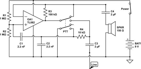
op amp Could someone help me understand this simple circuit
The circuit operates in receive mode, with the Push-To-Talk (PTT) switch enabling transmit mode. The speaker functions as both a microphone and a speaker. Most systems observed utilize a rocking armature transducer for the speaker. There is no base station...

Buffered breakout box
The monitoring circuit consists of four tri-color LEDs driven by an equal number of operational amplifiers configured as inverting amplifiers with a gain of one. Each LED is wired such that it illuminates red when the input to the op...

Inverting-programmable-gain-amplifier
This circuit can be programmed for a gain of 0, -1, -2, -4, or -8. This could also be accomplished with one input resistor and one feedback resistor per channel in the conventional manner, but this would require eight resistors...
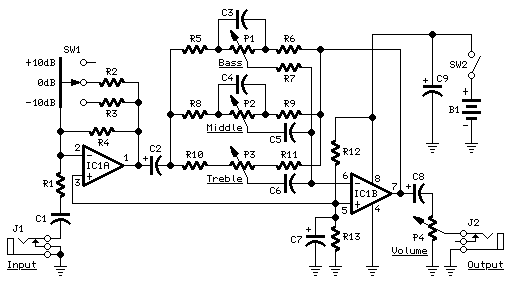
Audio Guitar Control
This preamplifier is designed as a portable unit, ideal for amplifying signals generated by guitar pickups, particularly the "bug" types used with acoustic instruments. It can be utilized with any type of device and pickup. The unit features a -10dB,...

Guitar Circuits Amps and Effects
A collection of guitar fuzz, preamp, and operational amplifier (op-amp) electronic circuits and schematics designed for various guitar effects and distortion effects.
This compilation includes a diverse range of electronic circuits that cater to guitarists seeking to enhance their sound with...

Signal Meter circuit
The operational amplifier (op-amp) used in the signal meter circuit is the TL061. The LF351 can also be used interchangeably, as it has the same pin layout. For those using a TL062 or similar models, the differing pin configurations are...