


headphone jacks
#headphone jack
#audio coupling
#PC audio
#telephone line
#audio transformer
#Eagle layout
#female connector
#speaker connection
#pin connections
#audio interface

Description: The inquiry pertains to the female connector utilized in a PC for connecting speakers, specifically regarding the pin connections of the jacks. The individual is also seeking guidance on the audio transformer ratings and size, mentioning the use of the Eagle layout editor software. The female connector on the sound card is identified as a standard stereo socket with three terminals for the left channel, right channel, and ground. It is noted that instead of RCA jacks, mono headphone jacks and corresponding female mono sockets may be used in the circuit. An audio isolation transformer with four terminals on one end and three terminals on the other is mentioned, along with a request for a connection diagram to interface this transformer with the telephone line and PC. The transformer is described as having two separate coils, with the phone line connected to one coil and the sound card line-in or line-out connected to the terminals on the other side. Impedance measurements indicate approximately 48 ohms on the telephone side and around 86 ohms on the PC side. Although an RC schematic with zener diodes has been implemented successfully, the audio level from the PC to the telephone side is reported as very low. Attempts to use an RC-coupled audio amplifier circuit on the telephone side have not yielded results, and assistance is requested to amplify the audio signal on the telephone side.
The female connector in question is a standard 3.5mm stereo socket, which typically features three pins: Tip (left channel), Ring (right channel), and Sleeve (ground). This socket interfaces with a corresponding male stereo jack, allowing for the transmission of audio signals from the PC to external devices. In the context of audio coupling between a PC and a telephone line, an audio isolation transformer is employed to prevent ground loops and ensure signal integrity.
The audio isolation transformer, as described, has four terminals on one side and three on the other, indicating that it may consist of two separate coils. The configuration allows for one coil to be connected to the telephone line while the other coil connects to the sound card's output. The impedance measurements taken from the transformer suggest that the side connected to the telephone line has an impedance of approximately 48 ohms, which is suitable for typical telephone line applications. The other side, with an impedance of around 86 ohms, is appropriate for the PC audio output.
To enhance the audio signal transmitted to the telephone line, additional amplification may be required. Implementing an RC-coupled audio amplifier circuit could potentially address the low audio levels experienced. The amplifier should be designed to accommodate the impedance characteristics of the transformer and the telephone line. It is essential to ensure that the amplifier has sufficient gain to elevate the audio signal to an acceptable level for transmission over the telephone network.
In summary, the schematic design should integrate the stereo socket for audio input, the audio isolation transformer for signal coupling, and an appropriate audio amplifier to boost the signal strength before it reaches the telephone line. Careful consideration of component specifications, including transformer ratings and amplifier gain, is crucial for achieving optimal performance in this audio coupling application.actually i wanted to know about the female connector used in PC for connecting the speaker. i hope u got it. i wanted to know the pin connections of the jacks. i shall show u the circuit for the audio coupling of the PC to telephone line. also please suggest me the audio transformer ratings and size, actually im using the eagle layout editor softw are and wanted to know which audio transformer i must connect from the available library. The female connector in the soundcard is a simple stereo socket with 3 terminals for left ch, right ch and ground. The corresponding male stereo jack pin and it`s connections have been posted by TPS. Instead of the RCA jacks you may use mono headphone jacks and corresponding female(mono) sockets as shown in your ckt.
I have got the audio isolation transormer which has got 4 terminals at one end and 3 terminals at the other end. Can anyone tell me connection diagram for this transformer to interface with the telephone line and PC.
The 4 terminals on one side are probably 2 separate coils. If so you may connect your phone line to one coil and the soundcard line-in(or line-out) to 2 terminals on the other side. I measured the impedance of the transformer using the multi- meter and one side i got the impedance around 48 ohms ( which I used for the Telephone side) and on the another between the middle and either one I got the impedance of around 86 ohms ( which is used for the PC side).
and I used the the RC schematics with zener diodes what has been given this forum is working fine. But on the telephone side the audio what Iam getting from PC is very much low. and even i tried with RC Coupled audio amplifier circuit on the telephone side but i didn`t work out. Can anyone tell me how can I amplify this audio signal on the telephone side. I measured the impedance of the transformer using the multi- meter and one side i got the impedance around 48 ohms ( which I used for the Telephone side) and on the another between the middle and either one I got the impedance of around 86 ohms ( which is used for the PC side).
and I used the the RC schematics with zener diodes what has been given this forum is working fine. But on the telephone side the audio what Iam getting from PC is very much low. and even i tried with RC Coupled audio amplifier circuit on the telephone side but i didn`t work out. Can anyone tell me how can I amplify this audio signal on the telephone side.
The female connector in question is a standard 3.5mm stereo socket, which typically features three pins: Tip (left channel), Ring (right channel), and Sleeve (ground). This socket interfaces with a corresponding male stereo jack, allowing for the transmission of audio signals from the PC to external devices. In the context of audio coupling between a PC and a telephone line, an audio isolation transformer is employed to prevent ground loops and ensure signal integrity.
The audio isolation transformer, as described, has four terminals on one side and three on the other, indicating that it may consist of two separate coils. The configuration allows for one coil to be connected to the telephone line while the other coil connects to the sound card's output. The impedance measurements taken from the transformer suggest that the side connected to the telephone line has an impedance of approximately 48 ohms, which is suitable for typical telephone line applications. The other side, with an impedance of around 86 ohms, is appropriate for the PC audio output.
To enhance the audio signal transmitted to the telephone line, additional amplification may be required. Implementing an RC-coupled audio amplifier circuit could potentially address the low audio levels experienced. The amplifier should be designed to accommodate the impedance characteristics of the transformer and the telephone line. It is essential to ensure that the amplifier has sufficient gain to elevate the audio signal to an acceptable level for transmission over the telephone network.
In summary, the schematic design should integrate the stereo socket for audio input, the audio isolation transformer for signal coupling, and an appropriate audio amplifier to boost the signal strength before it reaches the telephone line. Careful consideration of component specifications, including transformer ratings and amplifier gain, is crucial for achieving optimal performance in this audio coupling application.actually i wanted to know about the female connector used in PC for connecting the speaker. i hope u got it. i wanted to know the pin connections of the jacks. i shall show u the circuit for the audio coupling of the PC to telephone line. also please suggest me the audio transformer ratings and size, actually im using the eagle layout editor softw are and wanted to know which audio transformer i must connect from the available library. The female connector in the soundcard is a simple stereo socket with 3 terminals for left ch, right ch and ground. The corresponding male stereo jack pin and it`s connections have been posted by TPS. Instead of the RCA jacks you may use mono headphone jacks and corresponding female(mono) sockets as shown in your ckt.
I have got the audio isolation transormer which has got 4 terminals at one end and 3 terminals at the other end. Can anyone tell me connection diagram for this transformer to interface with the telephone line and PC.
The 4 terminals on one side are probably 2 separate coils. If so you may connect your phone line to one coil and the soundcard line-in(or line-out) to 2 terminals on the other side. I measured the impedance of the transformer using the multi- meter and one side i got the impedance around 48 ohms ( which I used for the Telephone side) and on the another between the middle and either one I got the impedance of around 86 ohms ( which is used for the PC side).
and I used the the RC schematics with zener diodes what has been given this forum is working fine. But on the telephone side the audio what Iam getting from PC is very much low. and even i tried with RC Coupled audio amplifier circuit on the telephone side but i didn`t work out. Can anyone tell me how can I amplify this audio signal on the telephone side. I measured the impedance of the transformer using the multi- meter and one side i got the impedance around 48 ohms ( which I used for the Telephone side) and on the another between the middle and either one I got the impedance of around 86 ohms ( which is used for the PC side).
and I used the the RC schematics with zener diodes what has been given this forum is working fine. But on the telephone side the audio what Iam getting from PC is very much low. and even i tried with RC Coupled audio amplifier circuit on the telephone side but i didn`t work out. Can anyone tell me how can I amplify this audio signal on the telephone side.
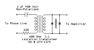
Audio interface for Telephone line
Audio from a telephone line can be obtained using a transformer and capacitor to isolate the line from external equipment. A non-polarized capacitor is placed in series with the transformer line connection to prevent DC current from flowing in the...
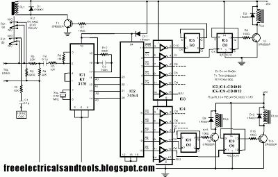
Remote Control Circuit Using KT3170
This circuit enables the switching on and off of appliances through telephone lines. It allows for the control of appliances from any distance, overcoming the limitations of infrared and radio remote controls. The circuit can manage up to nine appliances,...
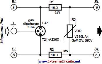
Protection For Telephone Line
A long time ago, when telephones were simple and reliable from an electrical standpoint, telecom operators installed surge protection on all telephone lines exposed to storm risks. Paradoxically, with the advent of delicate and expensive equipment such as electronic telephones,...

Telephone line monitors
This circuit is designed to detect tampering with a telephone line. It identifies if another telephone is connected, if there is a short circuit, or if the line is open. An audio alert and a flashing LED indicate the current...

Telephone Line Indicator
Utilizing an old moving coil instrument, it is straightforward to create a simple voltmeter that visually indicates the status of a telephone line. The circuit's high input impedance allows it to remain permanently connected to the line without drawing significant...
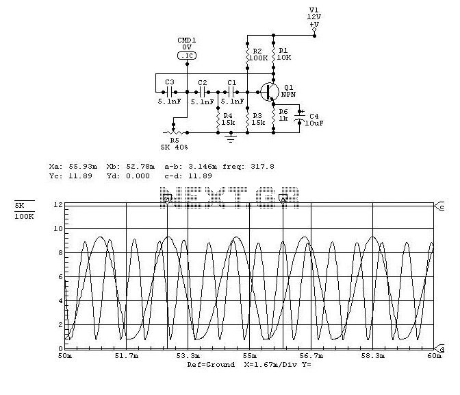
Telephone Audio Interface Schematic
Audio can be extracted from a telephone line using a transformer and a capacitor to isolate the line from external equipment. A non-polarized capacitor is placed in series with the transformer line connection to prevent direct current from flowing through...
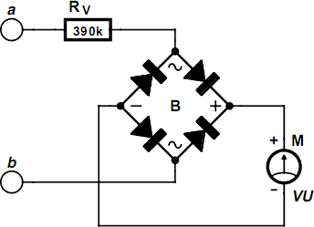
Telephone Line Indicator Circuit
Using an old moving coil instrument, it is easy to create a simple voltmeter that indicates the status of a telephone line at a glance. The circuit's high input impedance allows it to be permanently connected to the line, drawing...

Protection For Telephone Line
A long time ago, when telephones were simple and reliable from an electrical standpoint, telecom operators installed surge protection on all telephone lines exposed to storm risks. Ironically, this protection has diminished as more delicate and expensive equipment, such as...
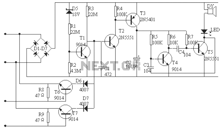
Telephone line burglar alarm circuit diagram
The phone alarm device is designed to monitor and prevent unauthorized use of a telephone line. When interference signals are detected on the line due to theft attempts, the alarm activates, preventing the thief from making calls while alerting the...