


LM2896 Car Audio Amplifier Circuit
#LM2896
#car audio
#amplifier
#stereo booster
#bridge technique
#power output
#audio circuit
#integrated amplifiers

Description: This car stereo booster utilizes an LM2896 integrated circuit, which features two amplifiers. It operates with supply voltages ranging from 3 to 15 volts. The power output is 2.5 watts per channel when connected to an 8-ohm load at a supply voltage of 12 volts. By employing a bridge configuration, the circuit can achieve a power output of 9 watts. The output can accommodate load impedances of either 4 ohms or 8 ohms, with the output power level being influenced by both the supply voltage and load impedance. This amplifier circuit is specifically designed to enhance the performance of automobile radio and cassette players. At maximum power output with a 4-ohm load, the current consumption reaches 1 ampere. An additional capacitor (Cx) and resistor (Rx) should be included in the circuit as indicated by the dashed lines in the schematic diagram. These components were taken into account during the design of the printed circuit board, and corresponding holes and soldering points are already provided. Instead of connecting two speakers, a single speaker should be used, connected to both output lines of the amplifier as shown by the dashed lines in the booster schematic. A speaker with either a 4-ohm or 8-ohm impedance can be utilized. To achieve a stereo system, a second amplifier circuit identical to the first must be constructed for the second channel.
The car stereo booster circuit is built around the LM2896 IC, which is a dual power amplifier designed for automotive audio applications. The circuit is capable of operating efficiently within a voltage range of 3 to 15 volts, making it versatile for various automotive power systems. The output power specifications indicate that the circuit can deliver 2.5 watts per channel under normal conditions with an 8-ohm load, which is suitable for typical car speakers.
When configured in a bridge mode, the circuit can provide a higher output power of 9 watts, which significantly enhances audio performance and volume levels. This bridge configuration allows for the utilization of both amplifiers within the LM2896 to drive a single speaker effectively, maximizing sound output without the need for additional components.
The choice of load impedance is critical; the circuit can accommodate both 4-ohm and 8-ohm speakers. The output power is contingent upon the supply voltage and the impedance of the connected load. For instance, at a supply voltage of 12 volts with a 4-ohm load, the circuit draws a maximum current of 1 ampere, which must be considered in the overall power supply design to ensure reliable operation without overloading the power source.
The inclusion of capacitor Cx and resistor Rx in the circuit is essential for stability and performance enhancement. These components aid in filtering and signal conditioning, ensuring that the audio output remains clear and distortion-free. The design of the printed circuit board incorporates specific provisions for these components, ensuring ease of assembly and reliability in the final product.
For stereo applications, it is recommended to construct an identical second amplifier circuit. This allows for true stereo sound by driving a second speaker, effectively utilizing both channels of the LM2896. Proper wiring and configuration will ensure that the audio experience in the vehicle is immersive and high-quality, meeting the demands of modern audio systems.This car stereo booster uses an LM2896 IC which has two integrated amplifiers. It can be powered with voltages up to 15 volts. The power output is 2. 5 watts per channel with an 8 © load and supply voltage of 12 volts. Using the bridge tehnique in the circuit gives a power output of 9 watts. The car audio booster can be powered up from 3 up to 15 volts. The load impedance that can be connected at its output can be either 4 © or 8 ©. The supply voltage and the load impedance influence the output power level. This amplifier circuit is designed as a booster for auto radio/cassette players. The current consumption by maximum power output and a 4 © load is 1 ampere. Add the additional capacitor Cx and the resistor Rx to the circuit as shown by the dashed lines in the schematic diagram. These parts were considered during the design phase of the printed circuit and appropriate holes, and soldering points are already available on the circuit board.
Instead of using 2 speakers, use a single speaker. Connect the speaker to both output lines of the amplifier as shown by the dashed lines in the booster schematic diagram. You can use either 4 © or 8 © speaker. Now, since only a single speaker is connected to the amplifier circuit, you must construct a second amplifier circuit identical to this one if you want a stereo system.
The second circuit will work for the second channel.
The car stereo booster circuit is built around the LM2896 IC, which is a dual power amplifier designed for automotive audio applications. The circuit is capable of operating efficiently within a voltage range of 3 to 15 volts, making it versatile for various automotive power systems. The output power specifications indicate that the circuit can deliver 2.5 watts per channel under normal conditions with an 8-ohm load, which is suitable for typical car speakers.
When configured in a bridge mode, the circuit can provide a higher output power of 9 watts, which significantly enhances audio performance and volume levels. This bridge configuration allows for the utilization of both amplifiers within the LM2896 to drive a single speaker effectively, maximizing sound output without the need for additional components.
The choice of load impedance is critical; the circuit can accommodate both 4-ohm and 8-ohm speakers. The output power is contingent upon the supply voltage and the impedance of the connected load. For instance, at a supply voltage of 12 volts with a 4-ohm load, the circuit draws a maximum current of 1 ampere, which must be considered in the overall power supply design to ensure reliable operation without overloading the power source.
The inclusion of capacitor Cx and resistor Rx in the circuit is essential for stability and performance enhancement. These components aid in filtering and signal conditioning, ensuring that the audio output remains clear and distortion-free. The design of the printed circuit board incorporates specific provisions for these components, ensuring ease of assembly and reliability in the final product.
For stereo applications, it is recommended to construct an identical second amplifier circuit. This allows for true stereo sound by driving a second speaker, effectively utilizing both channels of the LM2896. Proper wiring and configuration will ensure that the audio experience in the vehicle is immersive and high-quality, meeting the demands of modern audio systems.This car stereo booster uses an LM2896 IC which has two integrated amplifiers. It can be powered with voltages up to 15 volts. The power output is 2. 5 watts per channel with an 8 © load and supply voltage of 12 volts. Using the bridge tehnique in the circuit gives a power output of 9 watts. The car audio booster can be powered up from 3 up to 15 volts. The load impedance that can be connected at its output can be either 4 © or 8 ©. The supply voltage and the load impedance influence the output power level. This amplifier circuit is designed as a booster for auto radio/cassette players. The current consumption by maximum power output and a 4 © load is 1 ampere. Add the additional capacitor Cx and the resistor Rx to the circuit as shown by the dashed lines in the schematic diagram. These parts were considered during the design phase of the printed circuit and appropriate holes, and soldering points are already available on the circuit board.
Instead of using 2 speakers, use a single speaker. Connect the speaker to both output lines of the amplifier as shown by the dashed lines in the booster schematic diagram. You can use either 4 © or 8 © speaker. Now, since only a single speaker is connected to the amplifier circuit, you must construct a second amplifier circuit identical to this one if you want a stereo system.
The second circuit will work for the second channel.

simple-amplifier-with-c945mje340-and.html
This simple amplifier delivers good sound quality with a power output of approximately 10 to 14 Watts and operates on a supply voltage of about 34 to 36 Volts DC. It requires a preamplifier due to its limited advanced features....
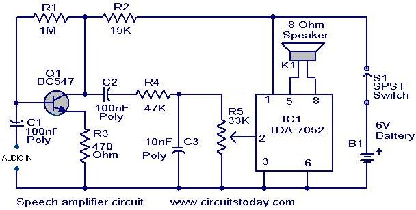
Speech amplifier circuit
This circuit can be housed within a box containing a speaker to create a convenient microphone amplifier. It is suitable for use by teachers, guides, lecturers, and others in crowded or noisy environments. The design is based on the audio...

The FARA 2 meter amplifier project
This article discusses a 2-meter amplifier capable of delivering an output of 25-30 watts. Over 35 units have been acquired at a cost of less than $50 each in bulk. Photo A displays the final version of the circuit board,...

Power Supply For Amplifiers
For the 60W amplifier, a nominal (full load) supply of +/- 35V is required, so a 25-0-25 secondary is ideal - however, see Updates, below. The circuit for the supply is shown below, and uses separate rectifiers, capacitors and fuses...
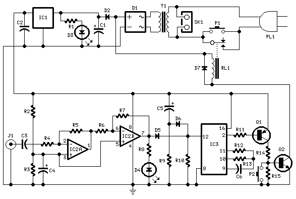
Amplifier Timer
Turns off your amplifier when idle for 15 minutes. Fed by amplifier tape-output. This circuit turns off an amplifier or any other device when a low-level audio signal fed to its input is absent for 15 minutes at least. Pushing...

20W Bridge Car Amplifier based TDA7240A
The following circuit diagram is a bridge amplifier specifically designed for car audio systems. The circuit is very simple, utilizing a few external components to support the power IC TDA7240A. This circuit will produce a maximum power output of...
The bridge...
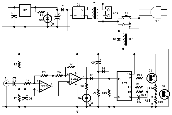
Amplifier Timer
This circuit turns off an amplifier or any other device when a low-level audio signal fed to its input is absent for 15 minutes at least. Pushing P1, the device is switched on, feeding any appliance connected to SK1. Input...
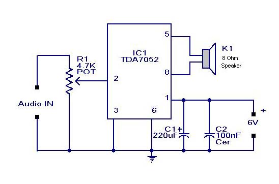
Small or Mini Audio Amplifier Circuit using TDA 7052 IC-Deliver 2 Watts
A compact audio amplifier circuit utilizing the TDA 7052 integrated circuit from Philips. This circuit is suitable for use as a pocket radio amplifier, delivering an output power of 2 watts.
The TDA 7052 is a low-voltage audio amplifier designed specifically...

Emitter negative feedback differential amplifier gain control circuit
A controllable gain amplifier functions as an automatic gain control circuit within the execution unit. The primary methods for controlling the amplifier's gain involve two approaches: one is by adjusting certain parameters of the amplifier itself, such as emitter current,...