


Low-distortion audio limiter circuit diagram
#audio limiter
#low-distortion
#operational amplifier
#level adjustment
#potentiometer
#signal processing
#audio processing
#sound engineering
#amplifier
#circuit design

Description: The AUD.LIMITER circuit features a level trim potentiometer that allows for adjustment of the limiting level. When the input signal exceeds the set level of the potentiometer, the output from one half of the operational amplifier, functioning as a comparator, activates the limit detector LED. This causes a rapid decrease in the resistance of the light-sensitive resistor. The other half of the operational amplifier increases the gain of the limiter. When the input signal falls below the desired limit level, the LED turns off, leading to an increase in the resistance of the photosensitive resistor, which in turn reduces the gain of the operational amplifier back to normal levels. The combination of resistors R1 and R2 determines the gain at these normal levels.
The AUD.LIMITER circuit is designed to regulate audio signal levels effectively, preventing distortion and ensuring consistent output. The circuit utilizes an operational amplifier configured in a comparator mode, which monitors the input signal against a reference voltage set by the trim potentiometer. The operational amplifier's output drives an LED, providing a visual indication of the limiting action.
In terms of operation, the circuit begins with an audio signal being fed into the non-inverting input of the operational amplifier. The trim potentiometer allows the user to set a threshold level, which is used as a reference voltage. When the audio signal exceeds this threshold, the output of the operational amplifier switches to a high state, illuminating the LED. This visual feedback is crucial for users to understand when the signal is being limited.
The light-sensitive resistor, also known as a photoresistor, plays a critical role in the feedback loop of the circuit. As the LED lights up, the resistance of the photoresistor decreases, which increases the gain of the operational amplifier limiter. This action helps to attenuate the audio signal, preventing it from exceeding the set limit and thereby protecting subsequent stages of the audio system from potential damage due to overdriving.
When the audio signal drops below the threshold, the LED turns off, and the resistance of the photoresistor increases. This change reduces the gain of the operational amplifier back to its normal operating levels, allowing the audio signal to pass through without additional attenuation. The resistors R1 and R2 are critical in establishing the gain of the operational amplifier in its normal state, ensuring that the circuit maintains the desired audio fidelity while providing effective limiting.
Overall, the AUD.LIMITER circuit is a valuable tool for audio engineers and technicians, providing a reliable means of controlling signal levels and preventing distortion in audio applications. Its design emphasizes simplicity and effectiveness, making it a practical choice for various audio processing tasks.AUD.LIMITER The level can limit level trim potentiometer to adjust. If you exceed the level of the potentiometer, the output from the half of the operational amplifier (as a co mparator) will limit detector LED lights, so light-sensitive resistor decreases rapidly. While the other half of the gain of the operational amplifier limiter will increase. When the signal falls below a desired limit level, the LED goes out, the photosensitive resistor increases limiter gain operational amplifier is reduced to normal levels, the combination of resistors R1 and R2 determine the gain of normal levels.
The AUD.LIMITER circuit is designed to regulate audio signal levels effectively, preventing distortion and ensuring consistent output. The circuit utilizes an operational amplifier configured in a comparator mode, which monitors the input signal against a reference voltage set by the trim potentiometer. The operational amplifier's output drives an LED, providing a visual indication of the limiting action.
In terms of operation, the circuit begins with an audio signal being fed into the non-inverting input of the operational amplifier. The trim potentiometer allows the user to set a threshold level, which is used as a reference voltage. When the audio signal exceeds this threshold, the output of the operational amplifier switches to a high state, illuminating the LED. This visual feedback is crucial for users to understand when the signal is being limited.
The light-sensitive resistor, also known as a photoresistor, plays a critical role in the feedback loop of the circuit. As the LED lights up, the resistance of the photoresistor decreases, which increases the gain of the operational amplifier limiter. This action helps to attenuate the audio signal, preventing it from exceeding the set limit and thereby protecting subsequent stages of the audio system from potential damage due to overdriving.
When the audio signal drops below the threshold, the LED turns off, and the resistance of the photoresistor increases. This change reduces the gain of the operational amplifier back to its normal operating levels, allowing the audio signal to pass through without additional attenuation. The resistors R1 and R2 are critical in establishing the gain of the operational amplifier in its normal state, ensuring that the circuit maintains the desired audio fidelity while providing effective limiting.
Overall, the AUD.LIMITER circuit is a valuable tool for audio engineers and technicians, providing a reliable means of controlling signal levels and preventing distortion in audio applications. Its design emphasizes simplicity and effectiveness, making it a practical choice for various audio processing tasks.AUD.LIMITER The level can limit level trim potentiometer to adjust. If you exceed the level of the potentiometer, the output from the half of the operational amplifier (as a co mparator) will limit detector LED lights, so light-sensitive resistor decreases rapidly. While the other half of the gain of the operational amplifier limiter will increase. When the signal falls below a desired limit level, the LED goes out, the photosensitive resistor increases limiter gain operational amplifier is reduced to normal levels, the combination of resistors R1 and R2 determine the gain of normal levels.

Operational Amplifier (Op-Amp) Oscillator
This is an operational amplifier (Op-Amp) oscillator circuit. This circuit has several advantages, including its ability to operate at low frequencies.
The operational amplifier oscillator circuit is designed to generate a periodic waveform output, typically a sine or square wave, using...

Wide band high frequency amplifier circuit
This is a wideband high-frequency amplifier circuit designed for a frequency range between 75-150 MHz. It utilizes a PNP transistor amplifier to enhance signal strength before it reaches the receiver of devices such as phones, FM radios, or amateur radios....
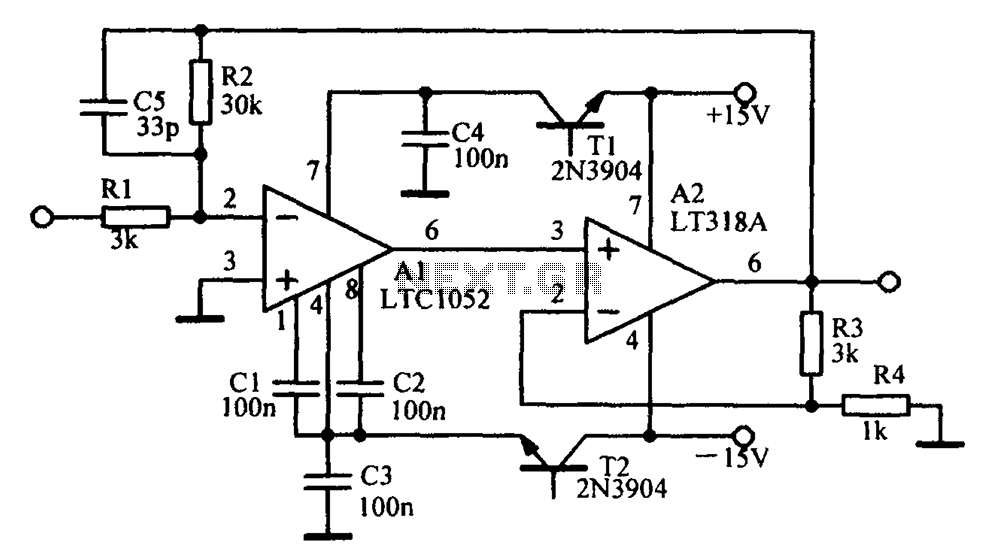
A circuit diagram of an amplifier circuit to enhance the output current and voltage
Amplifying circuit diagram to enhance the output current and voltage.
An amplifying circuit is designed to increase the amplitude of an input signal, resulting in a higher output current and voltage. This type of circuit is commonly utilized in various electronic...

iPod/MP3 Mini Speaker System
Listen and share music wherever you go with the mini speaker system project. This project allows for music playback in various locations such as dorms, cubicles, or the beach. It serves as an excellent introduction to circuit systems, featuring an...

Amplifier Clipping Indicator
At some stage, we will all find ourselves pushing hi-fi equipment just a little too hard, and if lucky, will just find that the sound has become "dirty". If this happens too often or is too severe, tweeters are the...

Self Oscillating Amplifier for Distortion Testing
The circuit is based on a simple inductor-capacitor filter circuit, and needs only a pot and a small light bulb to set and stabilise the oscillation. The frequency is fixed, and with a good inductor should be capable of very...

Amplifier Timer Circuit Schematic
This circuit turns off an amplifier or any other device when it remains idle for 15 minutes. It is powered by the amplifier's tape output.
The described circuit functions as an automatic power management system, designed to enhance energy efficiency by...
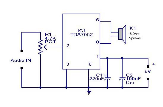
Small or Mini Audio Amplifier Circuit using TDA 7052 IC-Deliver 2 Watts
A compact audio amplifier circuit utilizing the TDA 7052 integrated circuit from Philips. This circuit is suitable for use as a pocket radio amplifier, delivering an output power of 2 watts.
The TDA 7052 is a low-voltage audio amplifier designed specifically...

Audio limiter circuit schematic
This audio limiter circuit is simple to construct and is compatible with BA741 operational amplifiers, whether in 8-pin or 4-pin configurations. It requires a symmetrical power supply. The circuit is designed to manage audio input levels effectively.
The audio limiter circuit...