


multiplexer with limiter and low pass
#stereo encoder
#BH1417
#pre-emphasis
#limiter
#low pass filter
#RF interference
#crystal oscillator
#audio transmission

Description: This design circuit is for a stereo encoder utilizing the BH1417 Stereo Encoder IC. The circuit incorporates pre-emphasis and a limiter to ensure consistent audio levels during transmission. A low-pass filter is included to block audio signals above 15 kHz, preventing RF interference. The BH1417 is a single-chip IC that operates on a voltage range of 6 to 15V and consumes approximately 25mA while delivering excellent sound quality with a channel separation of 40dB. The IC is available in an SOP22 package, which may pose a challenge for some users. However, its smaller size compared to traditional DIP-based ICs allows for the entire stereo coder to fit on a compact PCB. The circuit requires a 7.6 MHz crystal oscillator, which can be difficult to source, but a 7.68 MHz crystal can be used as an alternative without affecting the stereo encoding process. Testing has confirmed that the stereo sound remains crystal clear with this substitution.
The BH1417 Stereo Encoder circuit is designed to effectively encode stereo audio signals for transmission, ensuring high fidelity and minimal interference. The pre-emphasis stage enhances high-frequency sounds, which compensates for the inherent losses that occur during transmission. The limiter stage serves to prevent audio clipping, maintaining a consistent output level and enhancing the overall listening experience.
The low-pass filter is critical in this design, as it attenuates frequencies above 15 kHz, which are unnecessary for audio transmission and can contribute to RF interference. This filtering capability is essential in maintaining signal integrity and ensuring that the transmitted audio remains clear and free of unwanted noise.
The BH1417 IC's specifications allow it to operate efficiently within a supply voltage range of 6 to 15V, making it versatile for various applications. Its low current consumption of approximately 25mA is beneficial for battery-powered devices, extending operational life while maintaining sound quality. The impressive 40dB channel separation ensures that the left and right audio channels are distinctly reproduced, enhancing the stereo experience.
Although the BH1417 is housed in an SOP22 package, which may be less familiar to some engineers compared to DIP packages, its compact size facilitates the design of smaller PCBs. This is particularly advantageous in modern electronics where space is often a constraint.
For oscillator requirements, the use of a 7.68 MHz crystal in place of the specified 7.6 MHz crystal is a practical solution. The slight frequency difference does not adversely affect the encoding process, as confirmed by testing. This flexibility in component selection can simplify sourcing and reduce costs, making the design more accessible.
Overall, the BH1417 Stereo Encoder circuit represents an effective solution for transmitting high-quality stereo audio signals, combining advanced features with practical design considerations.This is a design circuit for stereo encoder. This circuit is using BH1417 Stereo Encoder. This circuit using with pre-emphasis, limiter so that the music can be transmitted at the same audio level, low pass filter that blocks any audio signals above 15 KHz to prevent any RF interference and crystal based stereo encoder for stereo transmission. Thi s is the figure of the circuit. The BH1417 single chip IC can be supplied with 6 - 15V voltage, consumes only around 25mA while providing very sound quality and improved 40dB channel separation. The IC is only available in SOP22 IC case and this may be an inconvenience for some folks. On the other hand, because the chip is smaller than regular DIP-based ICs it is possible to fit the entire stereo coder on a small PCB.
This IC is requires 7. 6MHz crystal oscillator which is pretty hard to find. The good news is that you can use 7. 68 MHz crystal instead. In fact our BH1417 stereo encoder prototype uses 7. 68 MHz crystal. This has absolutely no effect on stereo encoding process, we have tested it and stereo sound is crystal clear.
The BH1417 Stereo Encoder circuit is designed to effectively encode stereo audio signals for transmission, ensuring high fidelity and minimal interference. The pre-emphasis stage enhances high-frequency sounds, which compensates for the inherent losses that occur during transmission. The limiter stage serves to prevent audio clipping, maintaining a consistent output level and enhancing the overall listening experience.
The low-pass filter is critical in this design, as it attenuates frequencies above 15 kHz, which are unnecessary for audio transmission and can contribute to RF interference. This filtering capability is essential in maintaining signal integrity and ensuring that the transmitted audio remains clear and free of unwanted noise.
The BH1417 IC's specifications allow it to operate efficiently within a supply voltage range of 6 to 15V, making it versatile for various applications. Its low current consumption of approximately 25mA is beneficial for battery-powered devices, extending operational life while maintaining sound quality. The impressive 40dB channel separation ensures that the left and right audio channels are distinctly reproduced, enhancing the stereo experience.
Although the BH1417 is housed in an SOP22 package, which may be less familiar to some engineers compared to DIP packages, its compact size facilitates the design of smaller PCBs. This is particularly advantageous in modern electronics where space is often a constraint.
For oscillator requirements, the use of a 7.68 MHz crystal in place of the specified 7.6 MHz crystal is a practical solution. The slight frequency difference does not adversely affect the encoding process, as confirmed by testing. This flexibility in component selection can simplify sourcing and reduce costs, making the design more accessible.
Overall, the BH1417 Stereo Encoder circuit represents an effective solution for transmitting high-quality stereo audio signals, combining advanced features with practical design considerations.This is a design circuit for stereo encoder. This circuit is using BH1417 Stereo Encoder. This circuit using with pre-emphasis, limiter so that the music can be transmitted at the same audio level, low pass filter that blocks any audio signals above 15 KHz to prevent any RF interference and crystal based stereo encoder for stereo transmission. Thi s is the figure of the circuit. The BH1417 single chip IC can be supplied with 6 - 15V voltage, consumes only around 25mA while providing very sound quality and improved 40dB channel separation. The IC is only available in SOP22 IC case and this may be an inconvenience for some folks. On the other hand, because the chip is smaller than regular DIP-based ICs it is possible to fit the entire stereo coder on a small PCB.
This IC is requires 7. 6MHz crystal oscillator which is pretty hard to find. The good news is that you can use 7. 68 MHz crystal instead. In fact our BH1417 stereo encoder prototype uses 7. 68 MHz crystal. This has absolutely no effect on stereo encoding process, we have tested it and stereo sound is crystal clear.

Frequency crystal oscillator circuit diagram of 10kHz-150kHz
A transistor in series with capacitor C1 can be utilized to adjust the oscillator output frequency. The frequency may vary with changes in capacitance ranging from 20 pF to 0.01 µF, or as determined by the tuning capacitor. The transistor...

Third-overtone crystal oscillator
This circuit utilizes a 74S00 Schottky TTL gate. Additionally, no inductors are necessary.
The 74S00 is a dual 4-input NAND gate that operates at high speeds due to its Schottky technology, which minimizes propagation delay and power consumption. The circuit design...

96Mhz crystal oscillator
By utilizing a crystal oscillator operating between 27 and 33 MHz, the third harmonic frequency will produce an output ranging from 82 to 99 MHz.
The implementation of a crystal oscillator within the specified frequency range of 27 to 33 MHz...

Crystal oscillator provides low noise
The oscillator provides an output with high spectral purity while maintaining the typical stability associated with crystal oscillators. The crystal not only sets the oscillator's frequency but also functions as a low-pass filter to eliminate unwanted harmonics and as a...

Crystal oscillator-doubler
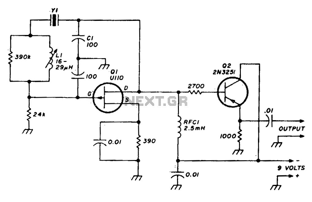
The crystal operates into a complex load at series resonance. L1, C1, and C2 balance the crystal at zero reactance. Capacitor C1 fine-tunes the center frequency. A tank circuit consisting of L2 and C3 doubles the output frequency, allowing the...
96Mhz crystal oscillator
A stable variable crystal oscillator (VXO) utilizing 6- or 8-MHz crystals employs a capacitor and an inductor to facilitate frequency pulling on either side of series resonance.
The described circuit operates as a variable crystal oscillator, which is crucial in applications...

One-Chip Crystal-Controlled Converter Circuit
This circuit operates effectively across a broad frequency spectrum. XTAL 1 serves as a fundamental-frequency crystal. Tl and CI are adjusted to match the input frequency. This circuit can be utilized as a straightforward shortwave converter for AM radios, among...

DIY Crystal Oscillator Circuit
A very simple DIY crystal oscillator circuit that uses a quartz crystal for frequency stability and a suitable RF transistor. It employs a second or third harmonic crystal for operation.
This DIY crystal oscillator circuit is designed to generate stable oscillations...

Crystal oscillator using TTL
The circuit operates using binary signal statuses of "1" and "0". It also incorporates a frequency generator.
The circuit described utilizes a binary signaling system, which is fundamental in digital electronics. The binary states "1" and "0" represent the two possible...