


Musical keyboard as a signal generator
#musical keyboard
#signal generator
#AC voltage
#impedance matching
#headphone jack
#frequency variable
#voice selection
#audio signal
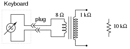
Description: An electronic musical keyboard serves as a source of variable-frequency AC voltage signals. It is not necessary to purchase an expensive keyboard; a model with at least a few dozen voice selections (such as piano, flute, harp, etc.) is recommended. The mono plug will connect to the headphone jack of the musical keyboard, so it is important to select a plug that fits properly. An impedance matching transformer, which can be easily obtained from an electronics supply store or scavenged from a small junk radio, connects between the speaker and the circuit board (amplifier) and is identifiable by its location. The primary winding is rated at 1000 ohms of impedance and is typically center-tapped, while the secondary winding is rated at 8 ohms and is not center-tapped. It is important to note that these impedance figures differ from DC resistance, so readings of 1000 ohms and 8 ohms should not be expected with an ohmmeter; however, the 1000-ohm winding will exhibit more resistance than the 8-ohm winding due to having more turns.
An electronics student would typically have access to a signal generator or function generator, which produces variable-frequency voltage waveforms for AC circuits. An inexpensive electronic keyboard serves as a more affordable alternative to a standard signal generator, offering features that many signal generators lack, such as the ability to produce mixed-frequency waves. To access the AC voltage generated by the keyboard, a plug must be inserted into the headphone jack (often labeled "phone") with two wires connected to custom circuits. Inserting the plug into the jack disconnects the built-in speaker (if present), making the signal that powered the speaker available at the plug wires. For this experiment, it is advisable to use the keyboard to power the 8-ohm side of an audio output transformer to step up the voltage to a higher level. If a power transformer is used instead of an audio output transformer, the connection should be made to the low-voltage winding, allowing it to operate as a step-up device. Since keyboards produce very low voltage signals, there is no shock hazard associated with this experiment.
Using an inexpensive Yamaha keyboard, it has been observed that the "panflute" voice setting produces the most accurate sine-wave waveform. This waveform, or a similar one (like the flute), is recommended for initial experiments as it is relatively free of harmonics, making it simpler for multimeter measurements. It is crucial to ensure that the keyboard is set to a mode that sustains the note while a key is held down; otherwise, the amplitude (voltage) of the waveform will fluctuate (high when the key is pressed and then rapidly decaying to zero). An AC voltmeter should be used to read the voltage directly from the headphone plug, followed by reading the voltage after it has been stepped up by the transformer, noting the step ratio. If the multimeter has a frequency function, it should be used to measure the frequency of the waveform produced by the keyboard. Different notes on the keyboard should be tried, and their frequencies recorded. Observations of frequency patterns, particularly among similar keys (noting the 12-key black-and-white pattern repeated across the keyboard), should be made. For convenience, frequencies in Hertz can be marked on the white keys in black ink, near the tops where they are less likely to be worn off by fingers. Ideally, there should be no change in signal amplitude (voltage) when testing different frequencies (notes on the keyboard). Adjusting the volume should reveal that changes in amplitude correspond with the volume setting.An electronic musical keyboard as a source of variable-frequency AC voltage signals. You need not purchase an expensive keyboard for this - but one with at least a few dozen "voice" selections (piano, flute, harp, etc. ) would be good. The "mono" plug will be plugged into the headphone jack of the musical keyboard, so get a plug that`s the correct size for the keyboard.
The "impedance matching transformer" is a small-size transformer easily obtained from an electronics supply store. One may be scavenged from a small, junk radio: it connects between the speaker and the circuit board (amplifier), so is easily identifiable by location. The primary winding is rated in ohms of impedance (1000 ©), and is usually center-tapped. The secondary winding is 8 © and not center-tapped. These impedance figures are not the same as DC resistance, so don`t expect to read 1000 © and 8 © with your ohmmeter - however, the 1000 © winding will read more resistance than the 8 © winding, because it has more turns.
Normally, a student of electronics in a school would have access to a device called a signal generator, or function generator, used to make variable-frequency voltage waveforms to power AC circuits. An inexpensive electronic keyboard is a cheaper alternative to a regular signal generator, and provides features that most signal generators cannot match, such as producing mixed-frequency waves.
To "tap in" to the AC voltage produced by the keyboard, you`ll need to insert a plug into the headphone jack (sometimes just labeled "phone" on the keyboard) complete with two wires for connection to circuits of your own design. When you insert the plug into the jack, the normal speaker built in to the keyboard will be disconnected (assuming the keyboard is equipped with one), and the signal that used to power that speaker will be available at the plug wires.
In this particular experiment, I recommend using the keyboard to power the 8 © side of an audio "output" transformer to step up voltage to a higher level. If using a power transformer instead of an audio output transformer, connect the keyboard to the low-voltage winding so that it operates as a step-up device.
Keyboards produce very low voltage signals, so there is no shock hazard in this experiment. Using an inexpensive Yamaha keyboard, I have found that the "panflute" voice setting produces the truest sine-wave waveform. This waveform, or something close to it (flute, for example), is recommended to start experimenting with since it is relatively free of harmonics (many waveforms mixed together, of integer-multiple frequency).
Being composed of just one frequency, it is a less complex waveform for your multimeter to measure. Make sure the keyboard is set to a mode where the note will be sustained as any key is held down - otherwise, the amplitude (voltage) of the waveform will be constantly changing (high when the key is first pressed, then decaying rapidly to zero). Using an AC voltmeter, read the voltage direct from the headphone plug. Then, read the voltage as stepped up by the transformer, noting the step ratio. If your multimeter has a "frequency" function, use it to measure the frequency of the waveform produced by the keyboard.
Try different notes on the keyboard and record their frequencies. Do you notice a pattern in frequency as you activate different notes, especially keys that are similar to each other (notice the 12-key black-and-white pattern repeated on the keyboard from left to right) If you don`t mind making marks on your keyboard, write the frequencies in Hertz in black ink on the white keys, near the tops where fingers are less likely to rub the numbers off. Ideally, there should be no change in signal amplitude (voltage) as different frequencies (notes on the keyboard) are tried.
If you adjust the volume up and down, you should discover that changes in amplitude should h
An electronics student would typically have access to a signal generator or function generator, which produces variable-frequency voltage waveforms for AC circuits. An inexpensive electronic keyboard serves as a more affordable alternative to a standard signal generator, offering features that many signal generators lack, such as the ability to produce mixed-frequency waves. To access the AC voltage generated by the keyboard, a plug must be inserted into the headphone jack (often labeled "phone") with two wires connected to custom circuits. Inserting the plug into the jack disconnects the built-in speaker (if present), making the signal that powered the speaker available at the plug wires. For this experiment, it is advisable to use the keyboard to power the 8-ohm side of an audio output transformer to step up the voltage to a higher level. If a power transformer is used instead of an audio output transformer, the connection should be made to the low-voltage winding, allowing it to operate as a step-up device. Since keyboards produce very low voltage signals, there is no shock hazard associated with this experiment.
Using an inexpensive Yamaha keyboard, it has been observed that the "panflute" voice setting produces the most accurate sine-wave waveform. This waveform, or a similar one (like the flute), is recommended for initial experiments as it is relatively free of harmonics, making it simpler for multimeter measurements. It is crucial to ensure that the keyboard is set to a mode that sustains the note while a key is held down; otherwise, the amplitude (voltage) of the waveform will fluctuate (high when the key is pressed and then rapidly decaying to zero). An AC voltmeter should be used to read the voltage directly from the headphone plug, followed by reading the voltage after it has been stepped up by the transformer, noting the step ratio. If the multimeter has a frequency function, it should be used to measure the frequency of the waveform produced by the keyboard. Different notes on the keyboard should be tried, and their frequencies recorded. Observations of frequency patterns, particularly among similar keys (noting the 12-key black-and-white pattern repeated across the keyboard), should be made. For convenience, frequencies in Hertz can be marked on the white keys in black ink, near the tops where they are less likely to be worn off by fingers. Ideally, there should be no change in signal amplitude (voltage) when testing different frequencies (notes on the keyboard). Adjusting the volume should reveal that changes in amplitude correspond with the volume setting.An electronic musical keyboard as a source of variable-frequency AC voltage signals. You need not purchase an expensive keyboard for this - but one with at least a few dozen "voice" selections (piano, flute, harp, etc. ) would be good. The "mono" plug will be plugged into the headphone jack of the musical keyboard, so get a plug that`s the correct size for the keyboard.
The "impedance matching transformer" is a small-size transformer easily obtained from an electronics supply store. One may be scavenged from a small, junk radio: it connects between the speaker and the circuit board (amplifier), so is easily identifiable by location. The primary winding is rated in ohms of impedance (1000 ©), and is usually center-tapped. The secondary winding is 8 © and not center-tapped. These impedance figures are not the same as DC resistance, so don`t expect to read 1000 © and 8 © with your ohmmeter - however, the 1000 © winding will read more resistance than the 8 © winding, because it has more turns.
Normally, a student of electronics in a school would have access to a device called a signal generator, or function generator, used to make variable-frequency voltage waveforms to power AC circuits. An inexpensive electronic keyboard is a cheaper alternative to a regular signal generator, and provides features that most signal generators cannot match, such as producing mixed-frequency waves.
To "tap in" to the AC voltage produced by the keyboard, you`ll need to insert a plug into the headphone jack (sometimes just labeled "phone" on the keyboard) complete with two wires for connection to circuits of your own design. When you insert the plug into the jack, the normal speaker built in to the keyboard will be disconnected (assuming the keyboard is equipped with one), and the signal that used to power that speaker will be available at the plug wires.
In this particular experiment, I recommend using the keyboard to power the 8 © side of an audio "output" transformer to step up voltage to a higher level. If using a power transformer instead of an audio output transformer, connect the keyboard to the low-voltage winding so that it operates as a step-up device.
Keyboards produce very low voltage signals, so there is no shock hazard in this experiment. Using an inexpensive Yamaha keyboard, I have found that the "panflute" voice setting produces the truest sine-wave waveform. This waveform, or something close to it (flute, for example), is recommended to start experimenting with since it is relatively free of harmonics (many waveforms mixed together, of integer-multiple frequency).
Being composed of just one frequency, it is a less complex waveform for your multimeter to measure. Make sure the keyboard is set to a mode where the note will be sustained as any key is held down - otherwise, the amplitude (voltage) of the waveform will be constantly changing (high when the key is first pressed, then decaying rapidly to zero). Using an AC voltmeter, read the voltage direct from the headphone plug. Then, read the voltage as stepped up by the transformer, noting the step ratio. If your multimeter has a "frequency" function, use it to measure the frequency of the waveform produced by the keyboard.
Try different notes on the keyboard and record their frequencies. Do you notice a pattern in frequency as you activate different notes, especially keys that are similar to each other (notice the 12-key black-and-white pattern repeated on the keyboard from left to right) If you don`t mind making marks on your keyboard, write the frequencies in Hertz in black ink on the white keys, near the tops where fingers are less likely to rub the numbers off. Ideally, there should be no change in signal amplitude (voltage) as different frequencies (notes on the keyboard) are tried.
If you adjust the volume up and down, you should discover that changes in amplitude should h

DIY Homemade Signal Generator with Pulse Width Modulation
Construct a signal generator using readily available components. It should produce a square wave with variable frequency and adjustable pulse width. This device can be utilized for various applications, including DC motor speed regulation, dimming of lamps or LEDs, transformer...

Audio-frequency generator circuit
An audio frequency signal generator can output audio signals, 465 kHz spectral amplitude signals, and 52.5 Hz to 16 kHz high-frequency amplitude-modulated signals. The high-frequency oscillator's vibration frequency is determined by the components G and L. A variety of musical...

4KHz-170MHz Wide Band RF Signal Generator I
Most commercial-grade signal generators provide more than just sinusoidal waveform output, but they tend to be expensive for casual use. This article presents a simple wideband signal generator built around Linear Technology's LTC6905 Silicon Oscillator, capable of generating frequencies from...

Audio signal control circuit
Audio signal control circuit. It illustrates a typical audio signal control circuit where two audio signals enter the integrated circuit through switching and tone controls (treble and bass), subsequently adjusting the output sent to the audio power amplifier.
The audio signal...

DC biasing audio signal
The audio source will be a line-level audio signal ranging from -2V to +2V AC, which will be passed through a 220µF coupling capacitor followed by a two-pole low-pass filter (RC). The signal will be processed by an Analog-to-Digital Converter...

AC polarity detection
The circuit should be capable of detecting voltages between 230 VAC and 120 VAC to 250 VAC, making it suitable for both US and EU applications. A non-isolated circuit was found, but it fails to simulate correctly due to ground...

Automatic AC voltage regulator circuit
Automatic AC voltage regulator circuit
The automatic AC voltage regulator circuit is designed to maintain a stable output voltage despite fluctuations in the input voltage. This circuit is essential for protecting sensitive electronic devices from voltage variations that can lead to...

1.8kHz signal generator circuit
The circuit depicted in the figure allows for the selection of optimal operating conditions and a suitable allocation of the temperature coefficient for the resonant circuit components. The resonance occurs at both ends of the circuit. Additionally, the exchange regulator...

Mini Audio Signal Generator
A small audio test generator is highly effective for quickly tracing signals through audio equipment. Its primary function emphasizes speed over precision. Typically, a single sine-wave signal of approximately 1 kHz suffices, and distortion levels are not critically important. However,...