


Overload protection circuit diagram of 25 ohm speaker
#speaker protection
#transistor
#overload protection
#audio circuit
#12V supply
#power management
#NB111EH/J
#NR001E
#650mW

Description: The overload protection circuit operates at a power of 650 mW with a supply voltage of 12 V and is designed for a speaker with an impedance of 25 ohms. The component specifications include: VT1 as transistor NB111EH/J, VT2 as transistor NR001E, VT3 as transistor NA11EB/J, and VT4 as transistor NA12EB/J.
The overload protection circuit is a critical component in audio systems, ensuring that speakers are safeguarded against excessive power levels that could lead to damage. This circuit operates at a power rating of 650 mW and is designed to function with a 12 V power supply. The speaker connected to this circuit has an impedance of 25 ohms, which is a common specification for many audio applications.
The circuit utilizes a series of transistors to monitor the current flowing to the speaker. The specifications of the transistors used are as follows: VT1 is a NB111EH/J transistor, which serves as the primary control element. It is responsible for detecting overload conditions and initiating protective measures. VT2, designated as NR001E, acts as an additional control element that assists in the switching operation, enhancing the responsiveness of the circuit under overload conditions.
Transistors VT3 and VT4, identified as NA11EB/J and NA12EB/J respectively, function as output drivers. They are designed to handle the current required by the speaker while also providing a fail-safe mechanism that disconnects the speaker from the power source in case of an overload. This arrangement not only protects the speaker but also ensures the longevity of the entire audio system.
In summary, the overload protection circuit is an essential feature in audio equipment, designed to prevent damage to speakers by utilizing a series of transistors that monitor and control the power delivered to the load. Proper selection of components, such as the specified transistors, is crucial for ensuring effective operation and reliability of the circuit. As shown in overload protection circuit power 650mW, supply voltage 12V, speaker 25 ohms. Part Component Specifications: VT1: transistor NB111EH/J VT2: Transistors: NR001E VT3: transistor NA11EB/J VT4: transistor NA12EB/J
The overload protection circuit is a critical component in audio systems, ensuring that speakers are safeguarded against excessive power levels that could lead to damage. This circuit operates at a power rating of 650 mW and is designed to function with a 12 V power supply. The speaker connected to this circuit has an impedance of 25 ohms, which is a common specification for many audio applications.
The circuit utilizes a series of transistors to monitor the current flowing to the speaker. The specifications of the transistors used are as follows: VT1 is a NB111EH/J transistor, which serves as the primary control element. It is responsible for detecting overload conditions and initiating protective measures. VT2, designated as NR001E, acts as an additional control element that assists in the switching operation, enhancing the responsiveness of the circuit under overload conditions.
Transistors VT3 and VT4, identified as NA11EB/J and NA12EB/J respectively, function as output drivers. They are designed to handle the current required by the speaker while also providing a fail-safe mechanism that disconnects the speaker from the power source in case of an overload. This arrangement not only protects the speaker but also ensures the longevity of the entire audio system.
In summary, the overload protection circuit is an essential feature in audio equipment, designed to prevent damage to speakers by utilizing a series of transistors that monitor and control the power delivered to the load. Proper selection of components, such as the specified transistors, is crucial for ensuring effective operation and reliability of the circuit. As shown in overload protection circuit power 650mW, supply voltage 12V, speaker 25 ohms. Part Component Specifications: VT1: transistor NB111EH/J VT2: Transistors: NR001E VT3: transistor NA11EB/J VT4: transistor NA12EB/J
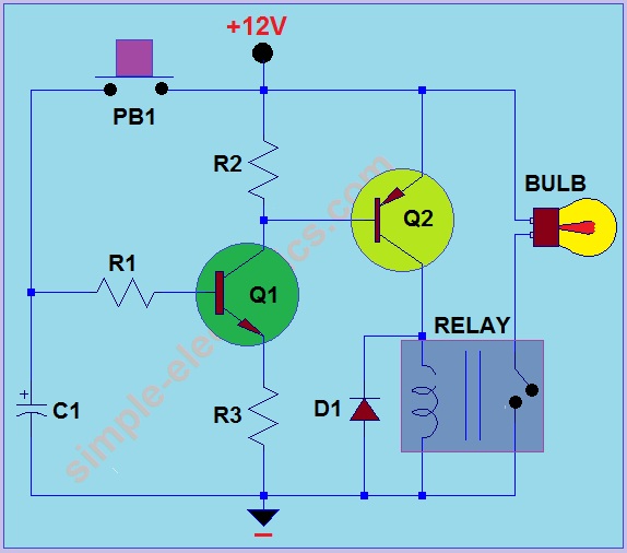
Car Headlight with Delay Circuit
This circuit operates by activating a headlight when the push-button PB1 is pressed. The headlight remains illuminated for a predetermined duration, which can range from several seconds to minutes, before automatically turning off. When PB1 is engaged, capacitor C1 begins...

Motor time division control circuit composed of transistor and NE555
Figure 2-32 (a) illustrates the time control diagram for a motor operated by switch S1. When S1 is set to position 1, the power driver circuit supplies current to the motor, enabling it to run. When S1 is switched to...

Transistor Based Burglar Alarm - Adding Extra Zones
The Transistor Burglar Alarm System allows for the addition of multiple extra zones. The primary circuit is compatible with standard normally-closed input devices, including magnetic reed contacts, micro switches, foil tape, and passive infrared sensors (PIRs). An auxiliary circuit provides...

modified battery charger circuit
Using a transistor will not yield accurate results, and the adjustment process can become quite tedious. The circuit is technically correct; if the tripping point can be adjusted properly, it may function as intended. Vinod states that he created a...
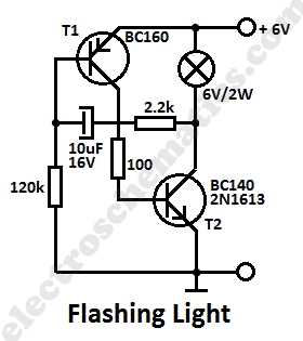
Flashing Light Circuit with Transistors
This simple flashing light circuit operates at 6 volts and 0.5A, exhibiting low current consumption when the light bulb is turned off. The frequency of the flashing is predetermined.
The circuit consists of a power supply, typically a battery or a...

Transistor attenuation - feedback tone circuit
Figure 4-11 illustrates a feedback attenuator that comprises a transistor-based tone control circuit. This circuit features a conventional high and bass control system, along with balance control, volume control, loudness adjustment, and subwoofer control, as well as field sense control....

Transistor Hartley Oscillator
Any vacuum-tube oscillator configuration has an equivalent transistor circuit. For example, consider the vacuum-tube oscillator, illustrated in Fig. 6-1 (A), which represents one form of Hartley oscillator. Positive feedback is accomplished by arranging the resonant tank E to be common...

SINGLE TRANSISTOR CODE PRACTICE OSCILLATOR
A 2N366 is configured as an audio feedback oscillator using an audio transformer. Adjust R1 for proper operation and the desired audio note.
The circuit utilizes a 2N366 transistor, which is a general-purpose NPN transistor, serving as the primary active component...

300B solid state
The classic 6-transistor circuit, prevalent in the 1960s and 70s, utilizes NPN output devices and features a relatively high bias level. It operates on a single rail, with input and output coupled through electrolytic capacitors. The design incorporates a clever...