


Parametric MID Frequence EQ
#parametric EQ
#mid frequency
#audio processing
#equalizer
#bass/treble control
#frequency adjustment
#audio filter
#signal processing
#sound engineering

The circuit under discussion serves as a natural progression of the Mic-Line balance unit, but it can also be tailored to fit any other audio circuit. The circuit is essentially two units connected in series: A) A classic bass/Treble unit, and B) a parametric unit designed for mid frequencies. These units are designed with flexibility in mind, and can be operated either jointly or independently, with the necessary buffer unit, from preceding and following circuits.
The circuit's functionality is further enhanced by the inclusion of various resistors that regulate different frequencies. For instance, the R2 resistor is used to regulate the high frequencies at +/- 18 dB/octave at 20 KHZ. Similarly, the R5 resistor is in place to control the low frequencies at +/- 18 dB/octave at 20 KHZ.
For mid frequencies, the circuit relies on the R11 resistor, which regulates the mid frequencies at +/- 15 dB/octave. Furthermore, the R10 resistor is responsible for the center of mid frequencies, operating within the 200 HZ - 6 KHZ band.
It's important to note that the circuit's design allows for a wide range of frequency regulation, making it adaptable to various audio applications. This adaptability, combined with the ability to operate the units both jointly and independently, makes this circuit a versatile tool in the field of audio electronics.The circuit constitutes a natural extension of Mic-Line balance unit, but can be adapted to any other audio circuit. It is made up of two units in the series : A) A classic unit bass/ Treble and B) a parametric unit of mid frequencies.
Both units can also be used autonomously or each one separately, with the required buffer unit, from previous and subsequent circuits. With the R2 we requlate the High frequencies +/- 18 db/oct at 20 KHZ, with R5 the Low frequencies +/- 18bd/oct at 20 KHZ, with R11 the Mid freq.
+/- 15 db/oct and with R10 the center of mid freq. at 200 HZ - 6 KHZ band.
The circuit's functionality is further enhanced by the inclusion of various resistors that regulate different frequencies. For instance, the R2 resistor is used to regulate the high frequencies at +/- 18 dB/octave at 20 KHZ. Similarly, the R5 resistor is in place to control the low frequencies at +/- 18 dB/octave at 20 KHZ.
For mid frequencies, the circuit relies on the R11 resistor, which regulates the mid frequencies at +/- 15 dB/octave. Furthermore, the R10 resistor is responsible for the center of mid frequencies, operating within the 200 HZ - 6 KHZ band.
It's important to note that the circuit's design allows for a wide range of frequency regulation, making it adaptable to various audio applications. This adaptability, combined with the ability to operate the units both jointly and independently, makes this circuit a versatile tool in the field of audio electronics.The circuit constitutes a natural extension of Mic-Line balance unit, but can be adapted to any other audio circuit. It is made up of two units in the series : A) A classic unit bass/ Treble and B) a parametric unit of mid frequencies.
Both units can also be used autonomously or each one separately, with the required buffer unit, from previous and subsequent circuits. With the R2 we requlate the High frequencies +/- 18 db/oct at 20 KHZ, with R5 the Low frequencies +/- 18bd/oct at 20 KHZ, with R11 the Mid freq.
+/- 15 db/oct and with R10 the center of mid freq. at 200 HZ - 6 KHZ band.

Ten-band-octave-equalizer
A series of active RF filters using the National LM3481C comprises a ten-band graphic equalizer. C1, C2, R1, and R2 should be at least 10% with 5% preferred tolerances.
The circuit design features a ten-band graphic equalizer that utilizes a series...

Audio Beat Detect ?« Electronic Product Design
This circuit employs a digital potentiometer to enable the microcontroller to automatically adjust the circuit's gain according to the ambient audio volume. However, a standard potentiometer can be used if automatic adjustment is unnecessary. The low-pass filter design is based...

M5227 five-band equalizer circuit
The M5227P is an application circuit designed for a graphic equalizer. Its control curve operates on a logarithmic frequency axis to represent the rate, requiring the same control curve pitch to ensure that all bands achieve maximum lift or total...

Middle Frequency Equalizer with Parametric Feature
An equalizer is a passive or active electronic component or circuit, such as tone control, designed to modify or flatten the frequency response characteristics of a system. The NE5532 is a low-noise, dual operational amplifier that features full power bandwidth...

10 band equalizer
The equalizer described is designed for hi-fi installations, public address systems, mixers, and electronic musical instruments. Relay contacts at the inputs and outputs, in conjunction with switch S2, allow for the selection of the desired channel. The input can be...

3 band equalizer circuit
This circuit is designed for tone control utilizing a three-band equalizer. It is based on the LF351 single-chip operational amplifiers. The circuit features three adjustable ranges: bass, mid, and treble controls. The equalizer allows for approximately +/-20 dB of boost...
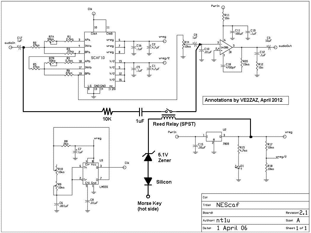
Nescaf mod
The NESCAF audio filter is a compact and cost-effective circuit that enhances amateur radio setups. It is particularly beneficial for radio receivers or transceivers that do not include an optional CW filter. However, one limitation of this filter is the...
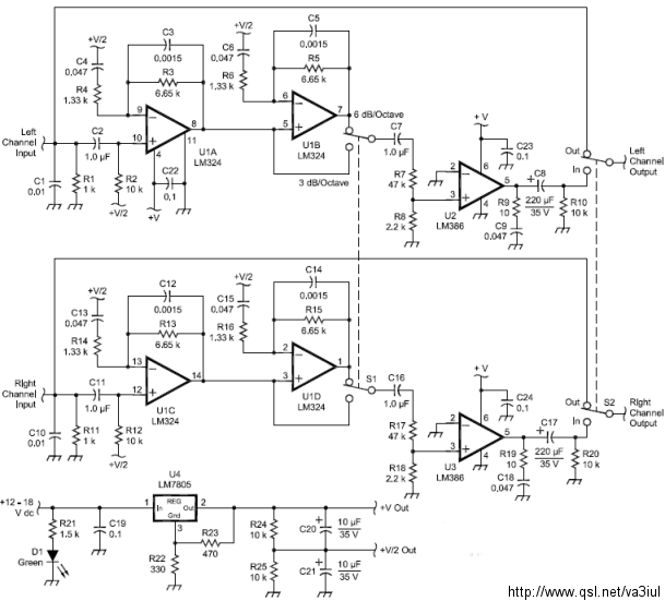
ARRL Handbook Audio Intelligibility Enhancer
Assistance is sought for building the N4GG audio intelligibility enhancer project as detailed in the ARRL Handbook. A circuit board has been ordered from Far Circuits, but there are difficulties in sourcing the necessary components. Attempts have been made to...

Audio Filter Analyzer
When this circuit is connected to a filter and an oscilloscope, the oscilloscope displays the filter's frequency response. A frequency that sweeps from low to high is applied to a filter. An oscilloscope is triggered by the start of the...