


Passive tone-control circuit
#passive
#tone control
#potentiometer
#audio
#filter
#bass
#treble
#sound adjustment
#standard components

Description: A simple circuit using two potentiometers and easily available standard value components provides tone control. The impedance level is suitable for low-level transistor or op-amp circuitry.
This tone control circuit typically employs two potentiometers to adjust the bass and treble frequencies of an audio signal. The configuration allows for fine-tuning of the audio output, enhancing the listening experience by allowing users to modify the tonal quality to their preference.
The circuit generally consists of two main sections: the bass control and the treble control. Each section utilizes a potentiometer connected in a voltage divider configuration. The output from each potentiometer is then fed into a summing amplifier, often implemented using an operational amplifier (op-amp). This configuration allows for the mixing of both frequency adjustments.
The potentiometers, often rated at 10kΩ, are chosen for their standard values, which are widely available and suitable for low-level audio signals. The impedance level of the circuit is designed to match that of typical low-level transistor or op-amp circuitry, ensuring compatibility and minimal signal loss.
Capacitors may also be included in the circuit to filter specific frequency ranges. For example, a capacitor can be placed in parallel with the bass potentiometer to allow lower frequencies to pass while attenuating higher frequencies. Similarly, a capacitor in the treble section can facilitate the passing of higher frequencies, enhancing the treble response.
Overall, this tone control circuit is an effective solution for audio applications, allowing for user-friendly adjustments to the tonal characteristics of the sound output while maintaining a low impedance level suitable for integration with various audio processing devices.A simple circuit using two potentiometers and easily available standard value components provides tone control. The impedance level is suitable for low-level transistor or op amp circuitry.
This tone control circuit typically employs two potentiometers to adjust the bass and treble frequencies of an audio signal. The configuration allows for fine-tuning of the audio output, enhancing the listening experience by allowing users to modify the tonal quality to their preference.
The circuit generally consists of two main sections: the bass control and the treble control. Each section utilizes a potentiometer connected in a voltage divider configuration. The output from each potentiometer is then fed into a summing amplifier, often implemented using an operational amplifier (op-amp). This configuration allows for the mixing of both frequency adjustments.
The potentiometers, often rated at 10kΩ, are chosen for their standard values, which are widely available and suitable for low-level audio signals. The impedance level of the circuit is designed to match that of typical low-level transistor or op-amp circuitry, ensuring compatibility and minimal signal loss.
Capacitors may also be included in the circuit to filter specific frequency ranges. For example, a capacitor can be placed in parallel with the bass potentiometer to allow lower frequencies to pass while attenuating higher frequencies. Similarly, a capacitor in the treble section can facilitate the passing of higher frequencies, enhancing the treble response.
Overall, this tone control circuit is an effective solution for audio applications, allowing for user-friendly adjustments to the tonal characteristics of the sound output while maintaining a low impedance level suitable for integration with various audio processing devices.A simple circuit using two potentiometers and easily available standard value components provides tone control. The impedance level is suitable for low-level transistor or op amp circuitry.

Simple Audio Clipper/Limiter
For use with headphones, this circuit sets the audio clipping level via a 5-kOhm potentiometer. This type of noise clipper is most effective for pulse-type noise with a low duty cycle, such as ignition noise. The resistor Rl establishes the...

4 order filter with a single IC project PCB
High-order circuit filters are typically designed using two or more cascaded sections. This fourth-order filter requires only one operational amplifier (OA) integrated circuit (IC), which helps achieve lower distortion and reduced intermodulation. The resistor values represent the load on the...

Electronic filter
An electronic filter is utilized to enhance the filtering effect of capacitor C5. Capacitors in this configuration form a composite circuit with the electronic filter, as illustrated in the accompanying figure. The advantage of using smaller capacitors (5 to 20...

tda2004-stereo-bridge-audio-amplifier.html
The TDA2004 integrated circuit (IC) is a popular choice among audio electronics enthusiasts due to its affordability and availability. This IC is often utilized in audio amplifier designs because it features two outputs and inputs, making it easy to implement...

Mini Audio Booster Amplifier
This small amplifier circuit is ideal for boosting small audio units.
The small amplifier circuit is designed to enhance the audio signals from low-output devices, such as microphones or portable music players. It typically employs a transistor or an operational amplifier...

Audio AGC amplifier circuit
The Audio Automatic Gain Control (AGC) circuit monitors the output signal level of an audio preamplifier. When the input signal increases, the AGC circuit automatically reduces the amplifier's gain. Conversely, when the input signal decreases, the AGC circuit increases the...

Broadband 0.1 to 10Hz filter amplifier
Broadband 0.1 to 10 Hz filter amplifier. The broadband circuit consists of two operational amplifiers configured as filter amplifiers operating in the frequency range of 0.1 to 10 Hz.
The broadband filter amplifier circuit utilizes two operational amplifiers (op-amps) to achieve...
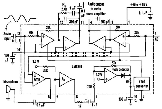
Gain-Controlled Amplifier
This single-chip circuit adjusts its audio gain according to the ambient noise picked up by the microphone. When operating in a quiet environment, the audio output is quiet, while a noisy environment results in a louder audio output. Audio to...

Audio VU meter with Extra wide Dynamic Range 69 dB using Arduino
After experimenting with a stereo version of the VU meter described in a previous blog post, a studio-grade VU meter is now being presented. This meter features 24 steps, spaced equally every 3 dB, and covers a wide dynamic range...