


Pocket-sized device to help Xin
#hearing aid
#portable
#input coupling capacitor
#filter capacitor
#bias signal
#audio amplifier
#low power
#medical device
#sound amplification
#miniature circuit

Description: The portable hearing aid circuitry includes several key components. Capacitor C1 serves as the input coupling capacitor, while C2 functions as the filter capacitor to prevent internal bias signals from affecting the input circuit. Capacitor C3 is utilized to attenuate high-frequency components from the headset BE. C4 acts as the power supply filter capacitor. The potentiometer RP is used for volume control. The audio signal is processed by the hearing aid microphone BM and the ASIC TB5318, which features internal multi-stage amplification, directly driving the headphones BE for playback. Due to the high gain of the circuit within IC1, careful attention must be paid to the layout of machine components to avoid self-excitation. Additionally, the pins of IC1 are connected to a resistor R, with a recommended value between 360KΩ and 1MΩ. The circuit design for BE should accommodate high-impedance headphones.
The portable hearing aid circuit is designed to enhance sound perception for users with hearing impairments. At the heart of the circuit, the input coupling capacitor C1 plays a critical role in coupling the audio signal from the microphone BM to the amplification stage. This capacitor blocks any DC component, allowing only the AC audio signals to pass through, which is essential for accurate sound reproduction.
Capacitor C2 is positioned strategically in the circuit to filter out any unwanted bias signals that may interfere with the audio input. This filtering action ensures that the integrity of the audio signal is maintained, providing a clearer sound experience for the user.
Capacitor C3 is specifically tasked with attenuating high-frequency noise that may originate from the headset BE. This is crucial for maintaining audio clarity, as excessive high-frequency components can lead to listener fatigue and discomfort.
The power supply filter capacitor C4 stabilizes the power supply voltage, ensuring that the circuit operates reliably without fluctuations that could affect performance.
Volume control is achieved through the potentiometer RP, allowing the user to adjust the output level to a comfortable listening volume.
The audio signal is amplified by the ASIC TB5318, which incorporates multiple amplification stages to ensure sufficient gain before the signal is sent to the headphones BE. It is important to note that the high gain provided by IC1 necessitates careful PCB layout design to prevent issues such as self-excitation, which can introduce unwanted noise into the audio signal.
The resistor connected to IC1 serves to set the gain of the amplifier circuit. The recommended resistance value of 360KΩ to 1MΩ allows for flexibility in adjusting the gain to suit different user requirements and headphone specifications.
Finally, the circuit design should ensure compatibility with high-impedance headphones, which are typically preferred for their sound quality and efficiency in converting electrical signals into audible sound. This consideration is essential for optimizing the performance of the hearing aid device. As shown for the portable hearing aid circuitry, which is the input coupling capacitor C1. C2 for the filter capacitor, to prevent internal bias signal input circuit caused by feedback. Capacitor C3 is used to appropriately attenuate high frequency components from the headset BE. C4 for the power supply filter capacitor. RP is the volume control potentiometer. ICl audio signal from the hearing aid microphone BM ASIC TB5318 internal multi-stage amplification, direct drive headphones BE playback. Due to the high gain of the circuit within IC1, pay attention to the wiring layout of the production of machine components, in order to avoid the formation of self-excited.
In addition, ICls feet have connected a resistor R value of the integrated circuit about stepper value should be 360K Omega ~ 1M Omega choose between. Circuit BE should be high impedance headphones.
The portable hearing aid circuit is designed to enhance sound perception for users with hearing impairments. At the heart of the circuit, the input coupling capacitor C1 plays a critical role in coupling the audio signal from the microphone BM to the amplification stage. This capacitor blocks any DC component, allowing only the AC audio signals to pass through, which is essential for accurate sound reproduction.
Capacitor C2 is positioned strategically in the circuit to filter out any unwanted bias signals that may interfere with the audio input. This filtering action ensures that the integrity of the audio signal is maintained, providing a clearer sound experience for the user.
Capacitor C3 is specifically tasked with attenuating high-frequency noise that may originate from the headset BE. This is crucial for maintaining audio clarity, as excessive high-frequency components can lead to listener fatigue and discomfort.
The power supply filter capacitor C4 stabilizes the power supply voltage, ensuring that the circuit operates reliably without fluctuations that could affect performance.
Volume control is achieved through the potentiometer RP, allowing the user to adjust the output level to a comfortable listening volume.
The audio signal is amplified by the ASIC TB5318, which incorporates multiple amplification stages to ensure sufficient gain before the signal is sent to the headphones BE. It is important to note that the high gain provided by IC1 necessitates careful PCB layout design to prevent issues such as self-excitation, which can introduce unwanted noise into the audio signal.
The resistor connected to IC1 serves to set the gain of the amplifier circuit. The recommended resistance value of 360KΩ to 1MΩ allows for flexibility in adjusting the gain to suit different user requirements and headphone specifications.
Finally, the circuit design should ensure compatibility with high-impedance headphones, which are typically preferred for their sound quality and efficiency in converting electrical signals into audible sound. This consideration is essential for optimizing the performance of the hearing aid device. As shown for the portable hearing aid circuitry, which is the input coupling capacitor C1. C2 for the filter capacitor, to prevent internal bias signal input circuit caused by feedback. Capacitor C3 is used to appropriately attenuate high frequency components from the headset BE. C4 for the power supply filter capacitor. RP is the volume control potentiometer. ICl audio signal from the hearing aid microphone BM ASIC TB5318 internal multi-stage amplification, direct drive headphones BE playback. Due to the high gain of the circuit within IC1, pay attention to the wiring layout of the production of machine components, in order to avoid the formation of self-excited.
In addition, ICls feet have connected a resistor R value of the integrated circuit about stepper value should be 360K Omega ~ 1M Omega choose between. Circuit BE should be high impedance headphones.

sound simple audio amplifier
The sound quality was poor, and then it stopped functioning. Can anyone explain which part of the circuit may have malfunctioned? Any suggestions to enhance the sound quality and restore functionality? The transistors used are both BC546, and the microphone...

class audio amplifiers
A Class-A audio amplifier is known for its high power consumption; however, its simplicity is appealing when ample power is available. This circuit features a Darlington transistor designed for use with a 5-volt power supply. It is important to note...

6w audio amplifier with preamplifier
The monolithic integrated audio amplifier circuit is specifically designed for portable radio and recorder applications, delivering up to 4 W into a 4-ohm load impedance. The power output is close to 6 watts RMS.
The monolithic integrated audio amplifier circuit is...

10W Audio Amplifier circuit based on TDA1910
This circuit is simple and inexpensive, which is its primary advantage. Although the output power is not high, the audio quality is good due to the TDA1910's low noise characteristics. This circuit is suitable for use as a student project.
The...

Single-chip audio power amplifier circuit
The Burr-Brown OPA541 chip is a power amplifier capable of operating with a maximum power supply voltage of 40V, delivering a continuous output current of up to 5A. The output current can be adjusted using an external resistor to protect...
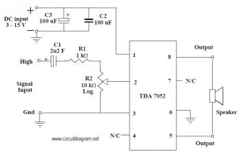
1W Mono Amplifier with TDA7052 circuit diagram
This is an audio amplifier circuit that uses the TDA7052 as the main component, along with five additional components to support its operation. The ideal supply voltage for this circuit is approximately 6-12V, and it does not require a heatsink.
The...

Low power regulator reference
This simple reference circuit provides a stable voltage reference that is nearly free from supply voltage noise. Typical power supply rejection exceeds 100 dB.
The described voltage reference circuit is designed to deliver a consistent output voltage while minimizing the influence...

LA4550 audio amplifier circuit 4W 8 ohm 12V operation
The LA4550 audio amplifier operates in a BTL (Bridge-Tied Load) configuration. This amplifier is capable of delivering 4W into an 8-ohm load when powered by a 12V power supply.
The LA4550 is designed for audio amplification applications, particularly in situations where...

Three-Level Audio Power Indicator circuit
This circuit is designed to indicate the power output level of any audio amplifier. It is simple, portable, and displays three power levels that can be set to any desired value.
The circuit operates by utilizing a combination of resistive voltage...