


Practical sound level monitor circuit diagram
#sound level monitor
#Schmitt trigger
#IC555
#acoustic detector
#voltage threshold
#audio measurement
#sound detection
#circuit diagram

Description: The acoustic detector consists of a Schmitt trigger IC555 connected to various components. When the input exceeds a certain voltage, the output will change state from high to low. R4 is used to set the threshold voltage.
The acoustic detector circuit utilizes the Schmitt trigger configuration of the IC555, which is known for its ability to provide hysteresis in switching applications. This characteristic is particularly useful in noise-sensitive environments, allowing the circuit to avoid false triggering due to small fluctuations in the input signal.
The primary function of the circuit is to detect acoustic signals that exceed a predefined threshold voltage. The input signal is fed into the non-inverting input of the Schmitt trigger. As the input voltage rises and crosses the threshold set by the resistor R4, the output of the IC555 transitions from a high state (logic 1) to a low state (logic 0). This transition can be utilized to activate further circuitry, such as alarms, indicators, or other control systems.
R4 plays a crucial role in defining the threshold voltage, and its value can be adjusted to tailor the sensitivity of the detector to specific acoustic levels. Additional components, such as capacitors and resistors, may be included in the circuit to filter out noise and stabilize the input signal, ensuring reliable operation.
Overall, this acoustic detector circuit is effective for applications requiring sound detection, such as security systems, sound-activated switches, and various automation tasks, where the precise detection of sound levels is critical.Acoustic detector consists of a Schmitt trigger IC555 connected components. Just input exceeds a certain voltage, its output will change state, from high to low. R4 to set the threshold voltage.
The acoustic detector circuit utilizes the Schmitt trigger configuration of the IC555, which is known for its ability to provide hysteresis in switching applications. This characteristic is particularly useful in noise-sensitive environments, allowing the circuit to avoid false triggering due to small fluctuations in the input signal.
The primary function of the circuit is to detect acoustic signals that exceed a predefined threshold voltage. The input signal is fed into the non-inverting input of the Schmitt trigger. As the input voltage rises and crosses the threshold set by the resistor R4, the output of the IC555 transitions from a high state (logic 1) to a low state (logic 0). This transition can be utilized to activate further circuitry, such as alarms, indicators, or other control systems.
R4 plays a crucial role in defining the threshold voltage, and its value can be adjusted to tailor the sensitivity of the detector to specific acoustic levels. Additional components, such as capacitors and resistors, may be included in the circuit to filter out noise and stabilize the input signal, ensuring reliable operation.
Overall, this acoustic detector circuit is effective for applications requiring sound detection, such as security systems, sound-activated switches, and various automation tasks, where the precise detection of sound levels is critical.Acoustic detector consists of a Schmitt trigger IC555 connected components. Just input exceeds a certain voltage, its output will change state, from high to low. R4 to set the threshold voltage.

Closed-loop three-phase multivibrator
This circuit is a closed loop consisting of three identical Schmitt triggers connected in series. Each flip-flop has a delay time of td = (RP + R)C, where C represents the capacitance and RP is the resistance in the circuit....
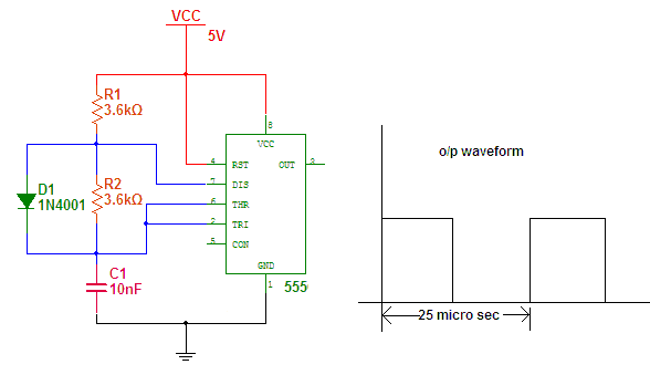
working with ic555
The IC555 is an on-chip multivibrator that allows the design of astable, monostable, and bistable multivibrators. Its primary applications include generating timing signals, clock waveforms, synchronizing signals, and square wave oscillators, among others. This document will discuss various applications of...
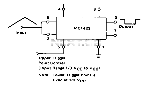
Schmitt trigger
The lower trigger point is fixed at a percentage of Vcc, while the upper trigger point can be adjusted using Pin 5, allowing it to vary from Vi to slightly less than Vcc. The Schmitt trigger is capable of operating...

Schmitt trigger comparator
The comparator features an output pull-up resistor (RL) and is configured to function as a Schmitt trigger using a single rail supply (Vcc). The feedback resistors (R1 and R2) establish upper and lower threshold levels (VT+ and VT-), respectively. The...

Schmitt trigger crystal oscillator
A Schmitt trigger provides effective squaring of the output, sometimes eliminating the need for an additional output stage.
A Schmitt trigger is a type of comparator circuit that incorporates hysteresis, which allows it to provide clean, stable output transitions. This characteristic...

Servo-Checker JR / Futaba
The first timer IC555 generates a negative trigger signal with a frequency of approximately 45Hz, producing a trigger impulse every 22ms. It is important not to exceed 50Hz for optimal servo performance. The second timer IC555 produces a modulated positive...

2 Siren Sound Use IC555 Schematic Diagram
The function of the Two Siren Sound Circuit utilizing IC 555 is divided into three parts: low frequency production, manufacturing of a shrill frequency, and low frequency output. The low frequency is generated by IC1, which is connected to an...

Voice relay circuit
The circuit consists of a sound detection circuit and a monostable trigger circuit that activates a relay. VT1 amplifies the input audio signal. When a signal is detected, the 555 timer is triggered, pulling K. Simultaneously, VT2 conducts, allowing the...

The SC (Schmitt Comparator) Head
I'll eventually post an explanation, but in the meantime, here it is. Meanwhile, a slightly refined version (with flashing LEDs to indicate "lock") was posted a few weeks later:
The provided description indicates a project involving a circuit that utilizes flashing...