


Resistor change
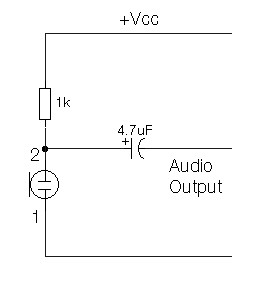
Description: Resistor change in ECM Mic Preamplifier schematic diagram. The electret condenser microphone (ECM) contains a highly sensitive microphone element and an internal FET preamplifier, necessitating a power supply within the range of 2 to 10 volts DC. Suitable ECMs can be sourced from Maplin Electronics. The schematic is illustrated for a three-terminal ECM, but two-terminal ECMs may also be utilized, with modifications detailed on the following page in the practical section.
The electret condenser microphone (ECM) is a popular choice for audio applications due to its high sensitivity and compact design. The internal FET preamplifier amplifies the weak audio signals generated by the microphone element, allowing for better signal processing and transmission. The power supply requirement of 2 to 10 volts DC is crucial for the proper operation of the internal circuitry.
When designing a preamplifier circuit for an ECM, it is essential to consider the resistor values used in the circuit, as they directly influence the gain and frequency response of the microphone. The schematic diagram typically includes a resistor connected to the microphone, which sets the biasing conditions for the FET.
In the case of a three-terminal ECM, the additional terminal usually serves as a ground or reference point, which is vital for noise reduction and signal integrity. For applications using a two-terminal ECM, adjustments must be made to the resistor values and circuit layout to accommodate the absence of the third terminal. This modification may involve connecting the circuit ground directly to the microphone casing or adjusting the biasing resistors to ensure optimal performance.
In practical applications, careful attention must be given to the layout of the circuit to minimize interference and maximize audio quality. Shielding may also be necessary to prevent electromagnetic interference from affecting the microphone's performance. The choice of components, such as capacitors and additional resistors, will further refine the preamplifier's response characteristics, ensuring compatibility with various audio processing systems.
Overall, the design and implementation of an ECM microphone preamplifier require a thorough understanding of both the microphone specifications and the associated electronic components to achieve the desired audio quality and functionality.Resistor change in ECM Mic Preamplifier schematic diagram. The electret condenser microphone (ECM) contains a very sensitive microphone element and an internal FET preamp, a power supply in the range 2 to 10 volts DC is therefore necessary. Suitable ECM`s may be obtained from Maplin Electronics. Although the schematic is drawn showing a three term inal ECM, two terminal ECM`s may be used, the following page in the practical section shows the changes.
The electret condenser microphone (ECM) is a popular choice for audio applications due to its high sensitivity and compact design. The internal FET preamplifier amplifies the weak audio signals generated by the microphone element, allowing for better signal processing and transmission. The power supply requirement of 2 to 10 volts DC is crucial for the proper operation of the internal circuitry.
When designing a preamplifier circuit for an ECM, it is essential to consider the resistor values used in the circuit, as they directly influence the gain and frequency response of the microphone. The schematic diagram typically includes a resistor connected to the microphone, which sets the biasing conditions for the FET.
In the case of a three-terminal ECM, the additional terminal usually serves as a ground or reference point, which is vital for noise reduction and signal integrity. For applications using a two-terminal ECM, adjustments must be made to the resistor values and circuit layout to accommodate the absence of the third terminal. This modification may involve connecting the circuit ground directly to the microphone casing or adjusting the biasing resistors to ensure optimal performance.
In practical applications, careful attention must be given to the layout of the circuit to minimize interference and maximize audio quality. Shielding may also be necessary to prevent electromagnetic interference from affecting the microphone's performance. The choice of components, such as capacitors and additional resistors, will further refine the preamplifier's response characteristics, ensuring compatibility with various audio processing systems.
Overall, the design and implementation of an ECM microphone preamplifier require a thorough understanding of both the microphone specifications and the associated electronic components to achieve the desired audio quality and functionality.Resistor change in ECM Mic Preamplifier schematic diagram. The electret condenser microphone (ECM) contains a very sensitive microphone element and an internal FET preamp, a power supply in the range 2 to 10 volts DC is therefore necessary. Suitable ECM`s may be obtained from Maplin Electronics. Although the schematic is drawn showing a three term inal ECM, two terminal ECM`s may be used, the following page in the practical section shows the changes.

Low Power Audio Amplifier
This circuit is designed to drive a low-power speaker using a sound effects module or a noise generator. It can also be utilized to create amplified speakers for computer use. The circuit amplifies the input signal by a factor of...
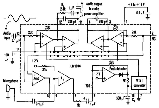
Gain-Controlled Amplifier
This single-chip circuit adjusts its audio gain according to the ambient noise picked up by the microphone. When operating in a quiet environment, the audio output is quiet, while a noisy environment results in a louder audio output. Audio to...

1 KHz Audio Oscillator schematic
This circuit consists of a CMOS square wave oscillator on a frequency of approximately 1 kHz. The RC filter, which has a roll-off frequency of 500 Hz, filters the harmonics, providing a sine-wave output.
The described circuit features a CMOS...

micprocessor
Audio processors are typically utilized in paging systems and wireless intercoms to amplify microphone signals to a specific level. This amplification can be achieved using either a compressor or a limiter circuit. While compressors exhibit lower distortion characteristics, they are...

FET Op Amp
The FM3954 monolithic dual provides an ideal low-offset and low-drift buffer function for the LM101A operational amplifier. It operates effectively over its bias current range.
The FM3954 is a dual operational amplifier designed to serve as a buffer for the LM101A,...

6-Meter preamplifier provides 20db gain
C1, C2, and C3 are miniature ceramic or plastic trimmers. T1 (main winding) has an inductance of 0.34 µH, utilizing 11 turns of No. 24 enameled wire wound on a T37-10 toroid core. The antenna winding consists of one turn,...
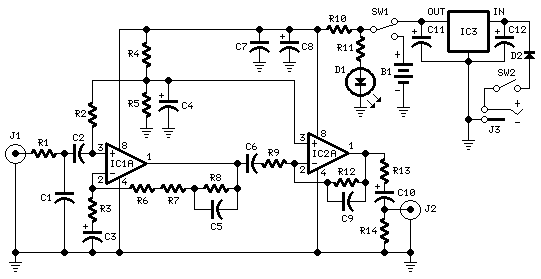
Portable Phone Preamplifier
This assembly is designed for amateurs who possess a collection of vinyl records and wish to convert them into a digital format on a personal computer. Alternatively, they may want to enjoy an old, cherished LP collection through their modern...

Microphone pre-amp
Cleaned Input:
Description: This circuit is used to give out a microphone preamp to an amplifier which will power the signal. The NPN transistors used are ECG123A. This circuit is also an older model to the one that now uses...

-15 V 1-A Regulated Power Supply
The supply receives -20 V from the rectifier/filter which is fed to the collector of the Darlington pnp pass transistor, a TIP105. The base drive to the TIP105 is supplied through resistor R5. The base of the TIP is driven...