


RIAA Phono Preamplifier

Description: Modern sound systems often lack inputs for record players, leading to a rise in the popularity of separate MD preamplifiers. These devices are essential not only for vinyl enthusiasts but also for individuals looking to digitize their LP collections onto CDs. The author has constructed numerous preamplifiers for friends and acquaintances, frequently utilizing an older circuit design featuring two µA741 op-amps, originally detailed by B. Wolfenden in a 1976 edition of Wireless World. In this straightforward design, the first op-amp amplifies the entire frequency spectrum, while the second incorporates RIAA frequency compensation, a common configuration of that era. Recently, a variation of this classic design emerged after some experimentation. This new version also employs two op-amps, but distributes the RIAA frequency compensation across both. The schematic diagram of this preamplifier illustrates that the first op-amp attenuates the signal at a rate of 6 dB/octave starting at 2.2 kHz, while the second op-amp manages the other corner frequency. The goal of this redesign was to maintain a high feedback factor in both stages. Surprisingly, this modification resulted in the reduction of audible scratches when records were played. The difference between the new and old preamplifiers was distinctly noticeable. A quick calculation revealed that a 0.05-mm scratch in a record groove, moving past a needle at a speed of 0.5 m/s, generates a square-wave pulse with a frequency of 10 kHz. This indicates that significant benefits can be achieved by attenuating such pulses with a low-pass filter as early as possible in the circuit, specifically in the first stage, to prevent them from over-driving subsequent stages.
The described preamplifier circuit utilizes two µA741 operational amplifiers to enhance the playback quality of vinyl records. The first op-amp serves as the primary amplification stage, boosting the signal while simultaneously implementing a low-pass filter effect. This filtering is critical as it mitigates high-frequency noise, such as that produced by scratches on the record surface. The design choice to implement the RIAA compensation across both op-amps rather than dedicating it solely to the second op-amp is a significant innovation. This approach allows for a more balanced frequency response and improves overall sound fidelity.
The first op-amp's configuration ensures that frequencies above 2.2 kHz are attenuated at a rate of 6 dB per octave, effectively reducing the impact of high-frequency artifacts that could otherwise distort the audio signal. The second op-amp, tasked with managing the lower corner frequency, completes the frequency compensation necessary for accurate vinyl playback. By distributing the RIAA compensation, the circuit can achieve a more nuanced handling of the audio signal, leading to clearer sound reproduction.
The unexpected benefit of reduced scratch audibility is a notable outcome of this design. By attenuating high-frequency pulses early in the signal chain, the circuit minimizes the potential for these artifacts to interfere with the desired audio output. This improvement not only enhances the listening experience but also demonstrates the importance of circuit design in audio applications. Overall, this preamplifier represents a thoughtful evolution of classic designs, tailored to meet the needs of modern audio enthusiasts while preserving the integrity of vinyl playback.Since modern sound systems usually lack inputs for record players, separate MD preampliers are becoming increasingly popular. They are needed not only by people who still regularly like to listen to vinyl records, but also by those who want tonally transcribe their LP collections to CD using a CD recorder.
The author has built innumerable p hono preamplifiers for friends and acquaintances. In many cases, for the sake of simplicity these were based on an old circuit design with two µA741s, which was originally described by B. Wolfenden in a 1976 issue of Wireless World. In that simple design, the first 741 simply amplied the full range of the frequency spectrum, while the second one was fitted with RIAA frequency compensation ” a fairly common conguration at that time.
However, a variant on this classic design was recently born after a bit of experimenting. It also uses two opamps, with the difference that the RIAA frequency compensation is distributed over both opamps. The accompanyinggure shows the schematic diagram of this preamplier. Therst opamp attenuates the signal at 6 dB/octave starting at 2. 2 kHz, while the second opamp looks after the other corner frequency. The objective of the new design was to keep the feedback factor as high as possible in both stages. To the considerable surprise of the developer, this modification turned out to have an unexpected side effect: when records were played, certain scratches were no longer audible!
The difference between the new and old preamplifiers could be clearly heard; it was certainly not just imagination. What could be the cause of this A quick calculation showed that a 0. 05-mm scratch in a record groove moving past a needle at a speed of 0. 5 m/s produces a square-wave pulse with a frequency of 10 kHz. Evidently, there is a lot to be gained by attenuating such pulses with a low-passlter as early as possible, which means in therst stage, in order to prevent them from over-driving the rest of the circuit.
The described preamplifier circuit utilizes two µA741 operational amplifiers to enhance the playback quality of vinyl records. The first op-amp serves as the primary amplification stage, boosting the signal while simultaneously implementing a low-pass filter effect. This filtering is critical as it mitigates high-frequency noise, such as that produced by scratches on the record surface. The design choice to implement the RIAA compensation across both op-amps rather than dedicating it solely to the second op-amp is a significant innovation. This approach allows for a more balanced frequency response and improves overall sound fidelity.
The first op-amp's configuration ensures that frequencies above 2.2 kHz are attenuated at a rate of 6 dB per octave, effectively reducing the impact of high-frequency artifacts that could otherwise distort the audio signal. The second op-amp, tasked with managing the lower corner frequency, completes the frequency compensation necessary for accurate vinyl playback. By distributing the RIAA compensation, the circuit can achieve a more nuanced handling of the audio signal, leading to clearer sound reproduction.
The unexpected benefit of reduced scratch audibility is a notable outcome of this design. By attenuating high-frequency pulses early in the signal chain, the circuit minimizes the potential for these artifacts to interfere with the desired audio output. This improvement not only enhances the listening experience but also demonstrates the importance of circuit design in audio applications. Overall, this preamplifier represents a thoughtful evolution of classic designs, tailored to meet the needs of modern audio enthusiasts while preserving the integrity of vinyl playback.Since modern sound systems usually lack inputs for record players, separate MD preampliers are becoming increasingly popular. They are needed not only by people who still regularly like to listen to vinyl records, but also by those who want tonally transcribe their LP collections to CD using a CD recorder.
The author has built innumerable p hono preamplifiers for friends and acquaintances. In many cases, for the sake of simplicity these were based on an old circuit design with two µA741s, which was originally described by B. Wolfenden in a 1976 issue of Wireless World. In that simple design, the first 741 simply amplied the full range of the frequency spectrum, while the second one was fitted with RIAA frequency compensation ” a fairly common conguration at that time.
However, a variant on this classic design was recently born after a bit of experimenting. It also uses two opamps, with the difference that the RIAA frequency compensation is distributed over both opamps. The accompanyinggure shows the schematic diagram of this preamplier. Therst opamp attenuates the signal at 6 dB/octave starting at 2. 2 kHz, while the second opamp looks after the other corner frequency. The objective of the new design was to keep the feedback factor as high as possible in both stages. To the considerable surprise of the developer, this modification turned out to have an unexpected side effect: when records were played, certain scratches were no longer audible!
The difference between the new and old preamplifiers could be clearly heard; it was certainly not just imagination. What could be the cause of this A quick calculation showed that a 0. 05-mm scratch in a record groove moving past a needle at a speed of 0. 5 m/s produces a square-wave pulse with a frequency of 10 kHz. Evidently, there is a lot to be gained by attenuating such pulses with a low-passlter as early as possible, which means in therst stage, in order to prevent them from over-driving the rest of the circuit.

Microphone Condenser Pre Amplifier Circuit
This is a simple preamplifier circuit designed for an electret condenser microphone, utilizing an LM1458 dual op-amp integrated circuit (IC). The circuit amplifies the audio signal from the condenser microphone, allowing it to be used as an input for devices...

Simple Car Preamplifier and Artificial Earth
The preamp circuit is completely conventional, and by necessity is AC coupled throughout. The artificial earth is derived by two resistors (R1 and R2), which will set the "earth" at exactly 1/2 the supply voltage. This is nominally 13.8V in...

preamplifier
This Hi-Fi stereo preamplifier circuit is designed with the TDA1054 IC from SGS. The TDA1054 is a 16-pin DIL integration that includes two separate preamplifier circuits. It is a low-noise preamp with minimal issues during the construction process. The first...

tape head preamplifier with LA3161
The Stereo Tape Head Preamplifier kit is based on LA3161 IC from SANYO. Power supply - 9 ~ 12 VDC @ 20 mA. Output power - upto 200 mW. Input Resistance - 100 KΩ (Typ), Load Resistance - 10 KΩ...
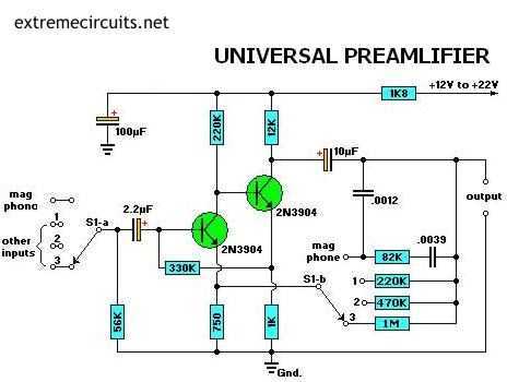
General use Preamplifier with 2N3904
Most audio amplifier systems must have preamplifiers with many different characteristics. These include high-gain linear response for magnetic microphones, low-gain linear response for tuners, and high-gain RIAA equalization for magnetic phone cartridges. To meet this broad requirement, most amplifier designers...

Hi-Fi Phono Preamplifier with RIAA Specification
The circuit was designed according to the RIAA implementation of a Hi-Fi phono preamplifier for the purpose of reproducing audio from a moving magnet cartridge.
The RIAA (Recording Industry Association of America) equalization curve is essential for the accurate playback of...
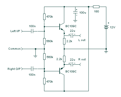
Audio Line preamp Driver
This preamplifier has a low output impedance, and is designed to drive long cables, allowing you to listen to a remote music source without having to buy expensive screened cables. The very low output impedance of around 16 ohms at...

Dynamic mic preamplifier circuit
This microphone preamplifier utilizes the low-noise integrated circuit (IC) uA739. It serves as a practical example of designing an effective preamplifier for dynamic microphones. The IC contains two identical integrated preamplifier circuits, with the second preamp functioning in the same...

RIAA Compensated Stereo Preamp
If a stereo amplifier lacks an input for a record player, it is advisable to utilize this circuit between the turntable and the amplifier. The output from the turntable adheres to a gain-bandwidth curve known as the RIAA compensation curve,...