


Soft-Action Mute Switch

Description: This simple circuit is a line-level audio signal muting switch based on a soft-action power on/off process. When the S1 switch is closed, R4, C1, and Q4 JFET are activated to mute the audio signal.
The circuit operates by utilizing a soft-action mechanism to control the muting of line-level audio signals. When the switch S1 is closed, it initiates the operation of the components R4, C1, and Q4. Resistor R4 is connected in series with the audio signal path, while capacitor C1 is used to provide a time delay for the muting action, allowing for a gradual reduction in audio output rather than an abrupt cut. This gradual muting is achieved through the charging and discharging characteristics of C1, which smooths the transition.
The JFET Q4 acts as a switch in this configuration. When S1 is activated, a small gate voltage is applied to Q4, allowing it to conduct and effectively mute the audio signal. The specific values of R4 and C1 can be adjusted to tailor the muting time constant to the desired effect, providing flexibility in the design. This circuit is particularly useful in audio applications where a smooth transition is preferable to prevent audible pops or clicks during signal interruption.
Overall, this line-level audio signal muting switch is an efficient and effective solution for managing audio signals in various electronic devices.This simple circuit is a line-level audio signal muting switch based on a soft-action power on/off process. When the S1 switch is closed, R4, C1 and Q4 JF..
The circuit operates by utilizing a soft-action mechanism to control the muting of line-level audio signals. When the switch S1 is closed, it initiates the operation of the components R4, C1, and Q4. Resistor R4 is connected in series with the audio signal path, while capacitor C1 is used to provide a time delay for the muting action, allowing for a gradual reduction in audio output rather than an abrupt cut. This gradual muting is achieved through the charging and discharging characteristics of C1, which smooths the transition.
The JFET Q4 acts as a switch in this configuration. When S1 is activated, a small gate voltage is applied to Q4, allowing it to conduct and effectively mute the audio signal. The specific values of R4 and C1 can be adjusted to tailor the muting time constant to the desired effect, providing flexibility in the design. This circuit is particularly useful in audio applications where a smooth transition is preferable to prevent audible pops or clicks during signal interruption.
Overall, this line-level audio signal muting switch is an efficient and effective solution for managing audio signals in various electronic devices.This simple circuit is a line-level audio signal muting switch based on a soft-action power on/off process. When the S1 switch is closed, R4, C1 and Q4 JF..

Transistor Based Burglar Alarm - Adding Extra Zones
The Transistor Burglar Alarm System allows for the addition of multiple extra zones. The primary circuit is compatible with standard normally-closed input devices, including magnetic reed contacts, micro switches, foil tape, and passive infrared sensors (PIRs). An auxiliary circuit provides...

Class AB Transistor Power Amplifier
Discrete Class AB Transistor Audio Power Amplifier Circuit Diagram. This is a Class AB transistor power amplifier. It is a simple amplifier.
The discrete Class AB transistor audio power amplifier is designed to provide efficient amplification of audio signals while minimizing...

Astable Multivibrator using transistors
The output can also be taken from the collector terminals of the transistors, as illustrated in the circuit below. To understand the operation of the circuit, it is recommended to read about how a transistor functions as a switch.
In a...
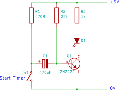
transistor timer
A single transistor timer circuit tutorial designed for beginners in electronics. This is an easy electronic circuit that can be constructed on a breadboard.
The single transistor timer circuit utilizes a transistor as the primary switching element to create a delay...
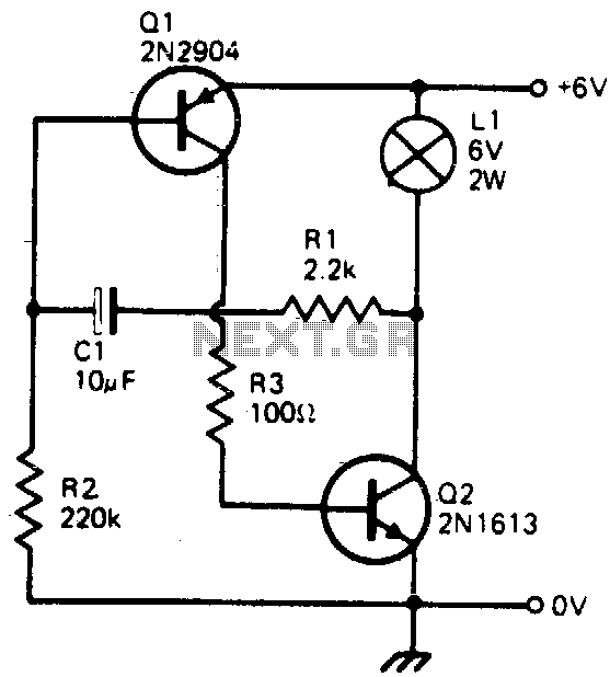
Transistorized flasher
This simple circuit will flash a 6-volt lamp at a rate determined by the size of capacitor C1. It is most economical on power as it only draws current when the lamp is on. When the lamp is off, both...

Two-phase squarewave oscillator
This circuit is one of the simplest to implement but can be challenging to comprehend. It consists of a two-transistor oscillator known as an astable multivibrator, which generates a square wave output that is out of phase. Initially, it is...

Single-junction transistor a phase-shift trigger circuit
Figure 16-29 (a) illustrates the trigger output through a resistor R2, while Figure 16-29 (b) depicts the integration of a programmable unidirectional transistor (PUT) trigger circuit. The adjustable potentiometer RP can modify the conduction angle of the TRIAC to facilitate...
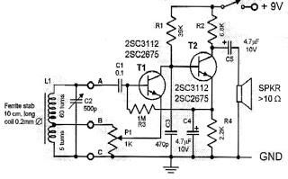
two transistor radio
This circuit is a simple one-transistor Audion type radio powered by a 1.5 V battery. It utilizes a pair of standard low-impedance headphones, wired in series to achieve a total impedance of 64 ohms. The power supply to the circuit...

Common emitter amplifier input and output signals of the phase relationship
The common emitter amplifier circuit exhibits a specific phase relationship between its input and output signals. This configuration is widely utilized in various electronic devices primarily for its high voltage gain. However, the output impedance is higher than the input...