


Strategic Dog Initiative
#bark detection
#analog delay line
#sound recording
#loudspeaker
#real-time processing
#CCD
#audio playback
#animal behavior
#noise cancellation
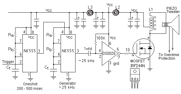
Description: The second method involves recording the actual bark in real-time using an analog CCD delay line with a delay of approximately 100 milliseconds. Upon recognizing the sound as a bark, the device plays back the last recorded 100 milliseconds of the bark through a loudspeaker. This confuses the dogs, causing them to shorten their barking until they often give up. It is amusing to observe their initial confusion. The third approach is effective during cold winter nights when the sounds of dogs can be heard throughout the neighborhood. It involves playing continuous white noise through a loudspeaker directed at the barking dog(s). This white noise seems to mask the sounds that trigger the dogs' barking. Caution is advised, as this could violate local noise ordinances, especially if nearby dog owners are sensitive to the noise. Regarding the type of pot core and winding used, several pot cores were stacked, with the primaries driven in parallel and the secondaries connected in series, ensuring correct phasing. This configuration was a quick method for achieving a "step-up" effect and providing sufficient power before core saturation occurs. The specifications of the pot core are relevant to the optimum operating frequency, which ranges from approximately 10 kHz to 40 kHz, peaking at around 20 kHz. However, this is not critical due to the broadband nature of ferrite transformers. Alternative transformer technologies, such as a single large ferrite toroid, could also be utilized. The frequency range of the circuit, as well as the ultrasonic hearing range of dogs, is typically above the human hearing range of approximately 20 kHz. Dogs can respond to frequencies up to 30 kHz or possibly higher. The primary intent is to avoid attracting the owner's attention while using enough power and directivity to capture the dog's attention.
The described circuit utilizes an analog CCD delay line for sound recording and playback, effectively creating a feedback loop that can alter a dog's barking behavior. The playback of the recorded bark serves as an auditory stimulus that confuses the dog, leading to a reduction in barking. The continuous white noise method operates on the principle of sound masking, where the introduction of a broad-spectrum noise signal effectively obscures other sounds that might trigger barking.
The circuit design includes a transformer configuration that allows for efficient power transfer and sound output. The choice of pot cores and winding arrangements is crucial for achieving the desired frequency response and minimizing distortion. The parallel connection of primary windings ensures that the input signal is evenly distributed, while the series connection of secondary windings increases the output voltage, effectively stepping up the signal for driving the loudspeaker.
The operating frequency range of the circuit, particularly the use of frequencies above 20 kHz, is significant as it falls within the ultrasonic range that is more perceptible to dogs than humans. This design consideration ensures that the device can effectively capture the attention of the dog without alerting the owner. The use of ferrite transformers is advantageous due to their broadband characteristics, allowing for flexibility in frequency response and efficiency in power handling.
Overall, the circuit not only aims to modify dog behavior through auditory stimuli but also incorporates considerations for sound masking and power efficiency, making it a multifaceted approach to addressing unwanted barking.The second method is to record (realtime) the actual bark in an analog CCD delay line (~100 msec FIFO) and upon recognition that the sound is a bark, the device plays back-through a loudspeaker-that last recorded 100 msec of bark. It really confuses them; they start shortening the number of their barks, until they often give up. It is funny t o watch/hear their initial confusion! 3) The third approach works well on cold winter nights when you can hear every dog in town, and so can your neighbors` dogs! It is continuous white noise played through a loudspeaker, toward the offending dog(s). This seems to "mask" the sounds that trigger the dog`s barking. Be careful however, because you could run afoul of your local noise ordinance-especially if your neighboring dog owner is "gunning" for you!
* What type of pot core and winding -Actually, I used several pot cores stacked, such that the primaries were driven in parallel and the secondaries were connected in series-all phased correctly. This was done as a quick & dirty way of achieving a "step up" and allow for enough power-before core saturation.
The specific pot core specs are only important relative to optimum operating frequency: ~10 kHz to ~40 Khz, peaking at ~ 20 kHz. However, this is not critical due to the broadband nature of ferrite transformers. One could use alternate transformer technology: single large ferrite torrid. * What is the freq range of the circuit (and a dogs ultrasonic hearing range, for that matter) -I have typically used a frequency above the human range ~ 20 kHz.
Dogs seem to respond to almost any frequency up to 30 kHz (and maybe above). My main intent was to not attract the owner`s attention, but use enough power & directivity to get the animal`s attention!
The described circuit utilizes an analog CCD delay line for sound recording and playback, effectively creating a feedback loop that can alter a dog's barking behavior. The playback of the recorded bark serves as an auditory stimulus that confuses the dog, leading to a reduction in barking. The continuous white noise method operates on the principle of sound masking, where the introduction of a broad-spectrum noise signal effectively obscures other sounds that might trigger barking.
The circuit design includes a transformer configuration that allows for efficient power transfer and sound output. The choice of pot cores and winding arrangements is crucial for achieving the desired frequency response and minimizing distortion. The parallel connection of primary windings ensures that the input signal is evenly distributed, while the series connection of secondary windings increases the output voltage, effectively stepping up the signal for driving the loudspeaker.
The operating frequency range of the circuit, particularly the use of frequencies above 20 kHz, is significant as it falls within the ultrasonic range that is more perceptible to dogs than humans. This design consideration ensures that the device can effectively capture the attention of the dog without alerting the owner. The use of ferrite transformers is advantageous due to their broadband characteristics, allowing for flexibility in frequency response and efficiency in power handling.
Overall, the circuit not only aims to modify dog behavior through auditory stimuli but also incorporates considerations for sound masking and power efficiency, making it a multifaceted approach to addressing unwanted barking.The second method is to record (realtime) the actual bark in an analog CCD delay line (~100 msec FIFO) and upon recognition that the sound is a bark, the device plays back-through a loudspeaker-that last recorded 100 msec of bark. It really confuses them; they start shortening the number of their barks, until they often give up. It is funny t o watch/hear their initial confusion! 3) The third approach works well on cold winter nights when you can hear every dog in town, and so can your neighbors` dogs! It is continuous white noise played through a loudspeaker, toward the offending dog(s). This seems to "mask" the sounds that trigger the dog`s barking. Be careful however, because you could run afoul of your local noise ordinance-especially if your neighboring dog owner is "gunning" for you!
* What type of pot core and winding -Actually, I used several pot cores stacked, such that the primaries were driven in parallel and the secondaries were connected in series-all phased correctly. This was done as a quick & dirty way of achieving a "step up" and allow for enough power-before core saturation.
The specific pot core specs are only important relative to optimum operating frequency: ~10 kHz to ~40 Khz, peaking at ~ 20 kHz. However, this is not critical due to the broadband nature of ferrite transformers. One could use alternate transformer technology: single large ferrite torrid. * What is the freq range of the circuit (and a dogs ultrasonic hearing range, for that matter) -I have typically used a frequency above the human range ~ 20 kHz.
Dogs seem to respond to almost any frequency up to 30 kHz (and maybe above). My main intent was to not attract the owner`s attention, but use enough power & directivity to get the animal`s attention!

Loudspeaker Tester
Testing loudspeakers is covered in some detail in the passive crossover article, but it is irksome at best to have to fiddle about with clip leads and components lying all over the workbench. This simple project is intended to make...

Loudspeaker Protector Monitors Current Circuit
When the voltage on the non-inverting input of each comparator exceeds the voltage at its inverting input, the output transitions to a high state, activating the corresponding LED. NOR gate latches are connected to the outputs of the third and...

Loudspeaker Protector Monitors Current
This circuit utilizes a 0.1Ω 1W resistor connected in series with the output of a power amplifier. When the amplifier delivers 100W into an 8Ω load, the resistor dissipates 1.25W. The temperature rise is detected by a thermistor thermally bonded...

Loudspeaker to Microphone converter circuit
This circuit utilizes a standard loudspeaker, enabling it to function as a microphone. It allows for the use of an inexpensive loudspeaker in this capacity. Sound waves impacting the speaker cone result in variations in the voice coil. The movement...

Novel loudspeaker coupling circuit
The ground side of the speaker is connected to the junction of two equal high-value capacitors (1000 µF is typical) across the supply. The amplifier output voltage will be Vs/2, and the voltage across CI (if CI and C2 are...

Loudspeaker as a Microphone
This circuit allows you to use a cheap loudspeaker as a microphone. Sound waves reaching the speaker cone cause fluctuations in the voice coil. The voice coil moving in the speaker's magnetic field will produce a small electrical signal.
The circuit...

Loudspeaker Protection
The detector circuit shown in Figure 1 is simple and works well, and as shown will not trigger with a 30V RMS signal at 5Hz, but operates in 60ms with 30V DC applied, and in 50mS with a 45V DC...

1980 RCA TC-2811 First Generation CCD Surveillance Camera
RCA developed some of the first commercially available CCD (Charge-Coupled Device) chips. A CCD is a silicon-based solid-state imaging device that replaces the older vidicon tubes. CCDs consist of a two-dimensional array of photodetectors linked to an array of shift...

Loudspeaker Box Amplifier schematic
This original design is a variation on a well-known design, examples of which can be found in a great many texts. My variation was to add a second differential stage to replace the usual common emitter-plus-constant current source. Doing so...