


Subsonic audio Filter
#subsonic filter
#Butterworth filter
#audio processing
#low frequency
#filter circuit
#resistors
#capacitors
#input impedance
#Q factor

Description: The circuit shown is completely conventional. The Q of the filters has been optimized to allow a higher input impedance than would otherwise be possible, with the final Q of the two filters being almost exactly 0.707 (i.e., a traditional Butterworth filter). Although in theory the tolerance of both resistors and capacitors should be 1% or better, in reality it is not that important. 1% metal film resistors are recommended (as always) but only for lowest noise, and capacitors are standard (i.e., 5% or 10%) tolerance. Yes, this will cause the response to deviate from that shown below (see Figure 2), but compared to other errors in the system (recording EQ, room LF node problems, etc.) these may be considered minor. At least one circuit that I know of uses a method of summing the channels below 140Hz, and although this is effective in removing the low frequency rumble (or sub-rumble in this case) component, it causes frequency response aberrations that are not acceptable. The subsonic frequencies generated by record warp are by nature out of phase. The mono component of a vinyl disc is lateral, whereas warp signals are vertical. Stereo signals are at 45°. The summing method was examined in great detail before deciding that it should not be used if the overall frequency response of the disc is to be preserved. Frequencies below 20Hz are usually not able to be reproduced, and with the exception of synthesizers and pipe organs, are not a wanted part of the audio spectrum. This is especially troublesome with phono systems, since many of the vinyl discs you treasure (or wish to transcribe to CD) will be warped to some degree. Any warp in a vinyl disc will cause large outputs in the subsonic region, typically well below 20Hz. For example, a 33 1/3 RPM album with a single warped section will create a signal in the pickup at 0.55 Hz (33.3 RPM / 60 = 0.555 Hz). This is a signal that will cause significant cone movement, but is undesirable in the extreme. Not only will vented subs be completely unable to handle such a signal linearly, but sealed subs will also be stressed. As can be seen from the above, below 2Hz the overall response is better than 90dB below the passband level - nominally anything below 17Hz is effectively disappeared. There is no reason to try to better this, as it already exceeds the resolution of any digital format and places all typical warp signals well below audibility or danger level for a sub-woofer.
The phase response is as one would expect for any filter, but it is important to note that unless the full-range signal is filtered, there may be unacceptable phase variations in the low frequency regions. Ideally, this filter should not be used in series with the sub-woofer amp, as the phase relationship between the main speakers and sub-woofer will be affected. However, it is probable that there will be no audible anomalies even if the P99 is installed in the subwoofer signal path. A power supply ground connection is necessary. The use of a PCB is recommended, as it simplifies the wiring process. Higher quality op-amps than the suggested TL072 dual versions may be used, with noise being the most critical parameter. Since the op-amps are wired as unity gain buffers, the upper frequency response will be well extended to beyond audibility.
Only a single channel is shown in the schematic, while the second channel utilizes the remaining op-amp in each of the dual packages. It is imperative that this circuit is driven from a low impedance source. The actual input impedance is greater than 47k at all frequencies, but the source impedance should ideally be no more than 100 ohms, although even a source impedance as high as 10k will cause few problems. If the full-range signal is to be passed through the filter, high-quality op-amps are recommended to prevent noise or distortion in the main signal. A switch may be incorporated to bypass the circuit when not in use. The use of a subsonic filter is not limited to vinyl discs; many CD recordings also contain subsonic energy, either deliberately or inadvertently.The circuit shown is completely conventional. The Q of the filters has been optimised to allow a higher input impedance than would otherwise be possible, with the final Q of the two filters being almost exactly 0.707 (i.e. a traditional Butterworth filter). Although in theory the tolerance of both resistors and capacitors should be 1% or better, in reality it is not that important.
1% metal film resistors are recommended (as always) but only for lowest noise, and capacitors are standard (i.e. 5% or 10%) tolerance. Yes, this will cause the response to deviate from that shown below (see Figure 2), but compared to other errors in the system (recording EQ, room LF node problems, etc.) these may be considered minor.
At least one circuit that the I know of uses a method of summing the channels below 140Hz, and although this is effective in removing the low frequency rumble (or sub-rumble in this case) component, it causes frequency response aberrations that (IMO) are not acceptable. The subsonic frequencies generated by record warp are by nature out of phase. The mono component of a vinyl disc is lateral, whereas warp signals are vertical. Stereo signals are at 45° The summing method was examined in great detail before deciding that it should not be used if the overall frequency response of the disc is to be preserved.
Frequencies below 20Hz are usually not able to be reproduced, and with the exception of synthesisers and pipe organs, are not a wanted part of the audio spectrum. This is especially troublesome with phono systems, since many of the vinyl discs you treasure (or wish to transcribe to CD) will be warped to some degree.
Any warp in a vinyl disc will cause large outputs in the subsonic region, typically well below 20Hz. For example, a 33 1/3 RPM album with a single warped section will create a signal in the pickup at 0.55 Hz (33.3 RPM / 60 = 0.555 Hz). This is a signal that will cause significant cone movement, but is undesirable in the extreme. Not only will vented subs be completely unable to handle such a signal linearly, but sealed subs will also be stressed.
As can be seen from the above, below 2Hz the overall response is better than 90dB below the passband level - nominally anything below 17Hz is effectively disappeared. There is no reason to try to better this, as it already exceeds the resolution of any digital format, and places all typical warp signals well below audibility or danger level for a sub-woofer.
The phase response is as one would expect for any filter, but it is important to note that unless the full-range signal is filtered, there may be unacceptable phase variations in the low frequency regions. Ideally, this filter should not be used in series with the sub-woofer amp, as the phase relationship between the main speakers and sub-woofer will be affected.
However, it is probable that there will be no audible anomalies even if the P99 is installed in the subwoofer signal path. wer supply ground connection. Naturally, I recommend that you use the PCB, as it makes a somewhat tedious wiring exercise very simple.
You may (as always) use better opamps than the TL072 dual versions suggested, and the most important parameter is noise. Since the opamps are wired as unity gain buffers, upper frequency response will be well extended to beyond audibility.
Only a single channel is shown in Figure 1, the second channel uses the remaining opamp in each of the dual packages. It is imperative that this circuit is driven from a low impedance. The actual input impedance is greater than 47k at all frequencies, but the source impedance should ideally be no more than 100 ohms or so (although as noted above, even as high as 10k will cause few problems).
If the full range signal is going to be passed through the filter, it is recommended that high quality opamps be used to prevent noise or distortion in the main signal. If desired, a switch may be used to bypass the circuit when not in use. The use of a subsonic filter is not reserved for vinyl discs - many CD recordings also contain subsonic energy as well, either deliberately or by accident!
The phase response is as one would expect for any filter, but it is important to note that unless the full-range signal is filtered, there may be unacceptable phase variations in the low frequency regions. Ideally, this filter should not be used in series with the sub-woofer amp, as the phase relationship between the main speakers and sub-woofer will be affected. However, it is probable that there will be no audible anomalies even if the P99 is installed in the subwoofer signal path. A power supply ground connection is necessary. The use of a PCB is recommended, as it simplifies the wiring process. Higher quality op-amps than the suggested TL072 dual versions may be used, with noise being the most critical parameter. Since the op-amps are wired as unity gain buffers, the upper frequency response will be well extended to beyond audibility.
Only a single channel is shown in the schematic, while the second channel utilizes the remaining op-amp in each of the dual packages. It is imperative that this circuit is driven from a low impedance source. The actual input impedance is greater than 47k at all frequencies, but the source impedance should ideally be no more than 100 ohms, although even a source impedance as high as 10k will cause few problems. If the full-range signal is to be passed through the filter, high-quality op-amps are recommended to prevent noise or distortion in the main signal. A switch may be incorporated to bypass the circuit when not in use. The use of a subsonic filter is not limited to vinyl discs; many CD recordings also contain subsonic energy, either deliberately or inadvertently.The circuit shown is completely conventional. The Q of the filters has been optimised to allow a higher input impedance than would otherwise be possible, with the final Q of the two filters being almost exactly 0.707 (i.e. a traditional Butterworth filter). Although in theory the tolerance of both resistors and capacitors should be 1% or better, in reality it is not that important.
1% metal film resistors are recommended (as always) but only for lowest noise, and capacitors are standard (i.e. 5% or 10%) tolerance. Yes, this will cause the response to deviate from that shown below (see Figure 2), but compared to other errors in the system (recording EQ, room LF node problems, etc.) these may be considered minor.
At least one circuit that the I know of uses a method of summing the channels below 140Hz, and although this is effective in removing the low frequency rumble (or sub-rumble in this case) component, it causes frequency response aberrations that (IMO) are not acceptable. The subsonic frequencies generated by record warp are by nature out of phase. The mono component of a vinyl disc is lateral, whereas warp signals are vertical. Stereo signals are at 45° The summing method was examined in great detail before deciding that it should not be used if the overall frequency response of the disc is to be preserved.
Frequencies below 20Hz are usually not able to be reproduced, and with the exception of synthesisers and pipe organs, are not a wanted part of the audio spectrum. This is especially troublesome with phono systems, since many of the vinyl discs you treasure (or wish to transcribe to CD) will be warped to some degree.
Any warp in a vinyl disc will cause large outputs in the subsonic region, typically well below 20Hz. For example, a 33 1/3 RPM album with a single warped section will create a signal in the pickup at 0.55 Hz (33.3 RPM / 60 = 0.555 Hz). This is a signal that will cause significant cone movement, but is undesirable in the extreme. Not only will vented subs be completely unable to handle such a signal linearly, but sealed subs will also be stressed.
As can be seen from the above, below 2Hz the overall response is better than 90dB below the passband level - nominally anything below 17Hz is effectively disappeared. There is no reason to try to better this, as it already exceeds the resolution of any digital format, and places all typical warp signals well below audibility or danger level for a sub-woofer.
The phase response is as one would expect for any filter, but it is important to note that unless the full-range signal is filtered, there may be unacceptable phase variations in the low frequency regions. Ideally, this filter should not be used in series with the sub-woofer amp, as the phase relationship between the main speakers and sub-woofer will be affected.
However, it is probable that there will be no audible anomalies even if the P99 is installed in the subwoofer signal path. wer supply ground connection. Naturally, I recommend that you use the PCB, as it makes a somewhat tedious wiring exercise very simple.
You may (as always) use better opamps than the TL072 dual versions suggested, and the most important parameter is noise. Since the opamps are wired as unity gain buffers, upper frequency response will be well extended to beyond audibility.
Only a single channel is shown in Figure 1, the second channel uses the remaining opamp in each of the dual packages. It is imperative that this circuit is driven from a low impedance. The actual input impedance is greater than 47k at all frequencies, but the source impedance should ideally be no more than 100 ohms or so (although as noted above, even as high as 10k will cause few problems).
If the full range signal is going to be passed through the filter, it is recommended that high quality opamps be used to prevent noise or distortion in the main signal. If desired, a switch may be used to bypass the circuit when not in use. The use of a subsonic filter is not reserved for vinyl discs - many CD recordings also contain subsonic energy as well, either deliberately or by accident!

Low frequency TTL oscillator
This oscillator utilizes standard inverters, one resistor, and one capacitor, and it does not have a minimum operating frequency. The resistor (R) and capacitor (C) must be selected to ensure that the currents flowing into the gates remain below the...

Low frequency oscillation circuit
Gates F4, F5, and F6 together form a low-frequency oscillator that drives high-brightness light-emitting diode (LED) flashes. The light-emitting diodes may be arranged around the booth seat for decorative purposes. The automatic referral machine is used prior to operation to...

Low frequency oscillator-flasher
Electrolytic capacitors are not required to generate a 1 cps frequency. When the silicon-controlled switch (SCS) is triggered, the 0.2 µF commutating capacitor deactivates the other capacitor and charges its gate capacitor to a negative potential. The gate capacitor charges...

muRata Manufacturing Measurement-Based SMT Capacitors
The schematic design of the equivalent circuit model for Murata Manufacturing's measurement-based GRH series SMT capacitors is derived from device measurements and modeling conducted by Murata. This model is applicable to capacitors mounted on an FR4 substrate, with constant substrate...
Capacitors
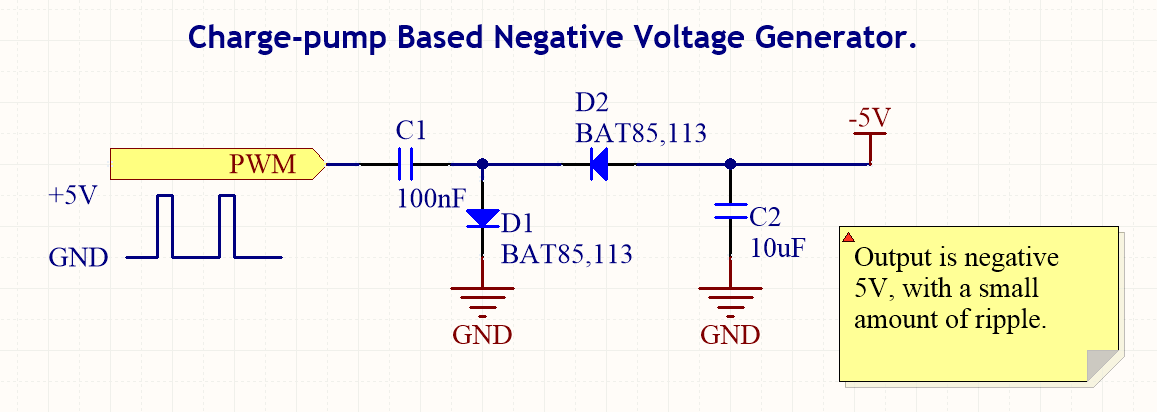
Capacitor types, their uses, formulas for common capacitance calculations, descriptions of charge pumps, information on dielectric soakage, and how to repair.
Capacitors are essential components in electronic circuits, serving various functions depending on their type and application. The primary types of...

how to build inexpensive frequency
Capacitors are major electronic components classified as passive components. They are extensively used in electronic circuits, and virtually no circuit can be constructed without these essential parts. The primary function of a capacitor is to block direct current (DC) while...

Low frequency divider
The ratio of capacitors C1 and C2 determines the division. With a positive pulse applied to the base of Q1, assume that C1 = C2 and that C1 and C2 are discharged. When Q1 turns off, both C1 and C2...
Low frequency crystal oscillator
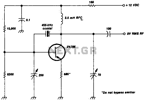
This crystal-oscillator circuit utilizes a 455-kHz crystal. It is a straightforward project.
The crystal oscillator circuit based on a 455-kHz crystal operates by utilizing the piezoelectric properties of the crystal to generate a stable frequency. The circuit typically consists of an...

Oscillator circuit
This circuit is a low-frequency Wien bridge sinusoidal oscillator designed for the audio range, characterized by very low distortion, making it suitable for testing various audio equipment. The circuit has undergone thorough testing, and a printed circuit board (PCB) is...