


Suppressor circuit diagram for singing karaoke
#karaoke
#buffer amplifier
#left channel
#right channel
#end-pass filter
#signal filtering
#audio processing
#amplifier

Description: The tape output circuit processes the left and right channel signals through a first buffer amplifier. The output signal is split into two paths: one route directly connects to an amplifier for amplification, while the other route passes through a low-pass filter for signal filtering. Signals are then sent through an amplifier subtractor, where a pair of left and right channel signals are subtracted. This subtraction effectively cancels out the main bass sound of the track, which is crucial for the song's structure. However, the attenuation of some other musical elements does not fully offset, allowing for the desired musical accompaniment and background music to remain. The output signal from the subtractor is then fed into a mixing amplifier for hybrid amplification. After this stage, the mixer output retains only the music's accompaniment, rhythm, and bass, while eliminating the vocal elements. The processed signal is sent to two buffer amplifiers, which amplify the left and right channel signals for the output equipment. The circuit's equilibrium potential is vital, as it regulates the intensity of the left and right channel signals, enhancing the suppression effect of the vocals.
The tape output circuit is designed to facilitate the separation and enhancement of musical elements within a stereo audio signal. The first buffer amplifier serves as an interface, isolating the input signals from the subsequent processing stages while preventing loading effects that could distort the audio quality. The low-pass filter is critical in removing high-frequency noise, ensuring that only the desired low-frequency components, such as bass, are forwarded to the amplifier.
The subtractor stage employs a differential configuration where the left and right channel signals are combined in such a way that common elements, primarily the vocal track, are canceled out. This technique is fundamental in karaoke applications, allowing the user to perform over the remaining instrumental tracks. The mixing amplifier further processes the signal, combining the filtered outputs to create a cohesive audio experience that emphasizes rhythm and harmony while minimizing competing vocal frequencies.
The final signal conditioning is achieved through two dedicated buffer amplifiers, which provide the necessary gain to drive the output equipment effectively. These amplifiers are configured to maintain a balanced output, ensuring that the left and right channels are equally represented. The equilibrium potential adjustment allows for fine-tuning of the signal levels, which is crucial for achieving a well-balanced mix and enhancing the overall listening experience. This comprehensive approach to signal processing ensures that the circuit achieves its intended purpose of delivering high-quality audio output while maintaining the integrity of the original musical elements.Tape output circuit by the left and right channel signals through the first buffer amplifier, the output signal of two routes, all the way directly to the amplifier amplifies the other way into the end-pass filter for filtering. Through signals sent via the amplifier subtractor by subtractors pair of left and right channel signals are subtracted. After subtraction, the same ingredient twice canceled track recording level, which is the main part of the song's bass sound; and twice trail recording level attenuation somewhat different ingredients but has not fully offset, this is desired musical accompaniment and background music.
The output signal of the subtractor is also fed into the mixing amplifier hybrid amplification. After this process, the signal output of the mixer in only retains the accompaniment of music, rhythm and bass music background music, but also eliminates the singing. The signal is sent to two buffer amplifiers, respectively, from the buffer amplifier output left and right channel signals for amplifying equipment.
Circuit equilibrium potential is very important, it is used to regulate the intensity of the left and right channel signals, to improve the effect of suppressing the song.
The tape output circuit is designed to facilitate the separation and enhancement of musical elements within a stereo audio signal. The first buffer amplifier serves as an interface, isolating the input signals from the subsequent processing stages while preventing loading effects that could distort the audio quality. The low-pass filter is critical in removing high-frequency noise, ensuring that only the desired low-frequency components, such as bass, are forwarded to the amplifier.
The subtractor stage employs a differential configuration where the left and right channel signals are combined in such a way that common elements, primarily the vocal track, are canceled out. This technique is fundamental in karaoke applications, allowing the user to perform over the remaining instrumental tracks. The mixing amplifier further processes the signal, combining the filtered outputs to create a cohesive audio experience that emphasizes rhythm and harmony while minimizing competing vocal frequencies.
The final signal conditioning is achieved through two dedicated buffer amplifiers, which provide the necessary gain to drive the output equipment effectively. These amplifiers are configured to maintain a balanced output, ensuring that the left and right channels are equally represented. The equilibrium potential adjustment allows for fine-tuning of the signal levels, which is crucial for achieving a well-balanced mix and enhancing the overall listening experience. This comprehensive approach to signal processing ensures that the circuit achieves its intended purpose of delivering high-quality audio output while maintaining the integrity of the original musical elements.Tape output circuit by the left and right channel signals through the first buffer amplifier, the output signal of two routes, all the way directly to the amplifier amplifies the other way into the end-pass filter for filtering. Through signals sent via the amplifier subtractor by subtractors pair of left and right channel signals are subtracted. After subtraction, the same ingredient twice canceled track recording level, which is the main part of the song's bass sound; and twice trail recording level attenuation somewhat different ingredients but has not fully offset, this is desired musical accompaniment and background music.
The output signal of the subtractor is also fed into the mixing amplifier hybrid amplification. After this process, the signal output of the mixer in only retains the accompaniment of music, rhythm and bass music background music, but also eliminates the singing. The signal is sent to two buffer amplifiers, respectively, from the buffer amplifier output left and right channel signals for amplifying equipment.
Circuit equilibrium potential is very important, it is used to regulate the intensity of the left and right channel signals, to improve the effect of suppressing the song.

Karaoke with integrated echo circuit
This fast circuit is compatible with any amplifier that has a line or high-level input (radio, CD) that allows mixing signals from a microphone with a chosen music source and adding adjustable sound effects to the voice. The circuit has...

Audio
This lab will demonstrate the theory and operation of non-inverting amplifiers as well as their practical application to amplify the signal of a microphone. A non-inverting amplifier will be constructed to increase the output signal of a microphone, which will...
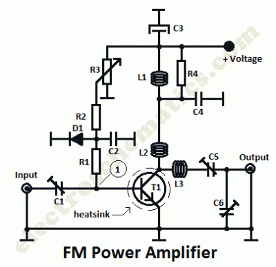
Radio Amplifiers Circuits
This is a 1 watt FM amplifier with a robust design that can be used to amplify an RF signal in the 88 to 108 MHz band. It is highly sensitive when utilizing quality RF power amplifier transistors, trimmers, and...

headphone monitor amp
This simple amplifier is designed to add a headphone jack to equipment that does not have this feature. The Headphone Buffer circuit board is compact (1.2" x 1.4"), allowing it to fit into even the smallest spaces, and its low...
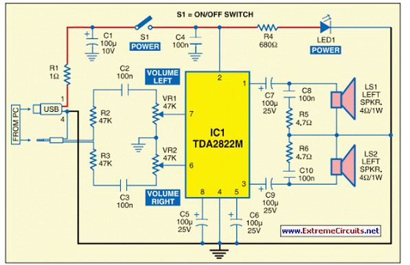
USB Powered Audio Power Amplifier
This circuit of multimedia speakers for PCs features a single-chip design, operates on a low-voltage power supply, is compatible with USB power, and allows for easy heat dissipation.
The multimedia speaker circuit is designed to enhance audio output for personal computers,...

5W-150mhz-amplifier
This circuit employs the MRF123 TMOS power FET. The MRF134 is a high-gain FET that may exhibit instability at both VHF and UHF frequencies. A 68-ohm input loading resistor has been used to improve stability. This amplifier achieves a gain...

Buffer-amplifier-for-multiplexers
The precision input characteristics of the HA-5147 simplify system error budgets, while its speed and drive capabilities enable fast charging of the multiplexer’s output capacitance. This speed eliminates increased multiplexer acquisition time, which can be induced by amplifiers with more...

circuit power audio amplifier with
This circuit is a complete application for a 2.1 amplifier system, featuring two satellite speakers for TDA and one subwoofer. It is commonly used in commercial applications to enhance the audio output of computers using a stereo amplifier along with...
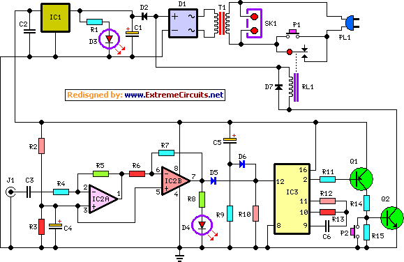
amplifier timer circuit schematic
This circuit deactivates an amplifier or any connected device when a low-level audio signal at its input is absent for at least 15 minutes. By pressing P1, the device is powered on, supplying power to any appliance connected to SK1....