


Talking Toy
#talking toy
#sound playback
#voice recording
#trigger circuit
#educational
#speaker
#playback module
#interactive
#toy electronics
#sound effects

Description: Talking toys, such as the popular Tickle Me Elmo and Furby, have been around for years. These devices respond to actions like being tickled or pressed, producing speech and sounds. This article explains how to build a talking circuit using the SpeakJet sound synthesizer chip, which allows for sound recording and playback. The chip connects to a computer with accompanying software for programming. Electrical signals generated by the computer correspond to recorded sounds, forming sentences, music, or sound effects. The SpeakJet chip can store eight sounds, controlled by specific pins on the integrated circuit (IC). The circuit is touch-activated, similar to talking toys. Key components include an amplifier to enhance audio signals, a speaker for sound output, resistors to limit current, capacitors for noise filtering, a MAX232 chip for signal conversion, switches for sound activation, and a DB9 connector for programming the chip.
The circuit design for a talking toy incorporates several essential components to facilitate sound playback and interaction. The SpeakJet sound synthesizer chip serves as the core of this circuit, allowing for the recording and playback of audio. This chip is programmable via a computer, utilizing a serial connection through a DB9 connector. The programming process involves sending electrical signals representing the desired sounds to the SpeakJet, which can store up to eight distinct sounds, though the current project limits this to three for simplicity.
The circuit is activated through three single-pole, single-throw (SPST) switches, which are connected to the SpeakJet's pins. These switches are normally open, meaning they connect to ground until pressed. When a switch is engaged, it raises the voltage on the corresponding pin, prompting the SpeakJet to output the programmed sound. This interaction mimics the functionality of popular talking toys, providing a tactile experience for users.
To ensure sound clarity and prevent distortion, an amplifier is utilized to boost the audio signal from the SpeakJet before it is output through the speaker. The circuit also incorporates various resistors and capacitors to manage current flow and filter out high-frequency noise. For instance, resistors R1, R2, and R3 limit current to ground when the switches are pressed, while capacitors C6 and C7, in conjunction with resistors R6 and R7, create low-pass filters to eliminate unwanted noise.
Powering the circuit requires a 4.5V supply, typically provided by a battery pack for three AAA batteries, although a DC power supply may also be used. The MAX232 chip plays a crucial role in converting the voltage levels from the computer to those compatible with the SpeakJet chip, ensuring accurate signal transmission.
In terms of physical implementation, the circuit can be enclosed within a toy, with the tactile switches strategically placed to allow for intuitive interaction. For example, switches can be positioned in various parts of the toy, such as the hand, stomach, or leg, enabling different sounds to be triggered based on user interaction. Jumper wires may be extended as needed to accommodate the desired placement of the switches.
Overall, this circuit design provides a comprehensive framework for creating a talking toy, leveraging the capabilities of the SpeakJet synthesizer chip and additional electronic components to deliver an engaging auditory experience.You`ve probably seen many of these toys. They`ve been around for years, from the talking tickle me elmo to the talking furby, like the one shown above. How do these devices do what they do when you perform an action such as tickle them or press a certain part of them How do they talk In this article, we will go over how you can build a circuit w
hich talks. The speakjet is a sound synthesizer chip which allows you to record sounds and then play back the prerecordered sounds. This is why they work perfectly to create devices such as talking toys. How it works is you connect this IC to a computer, and the chip comes with software so that you can program it to record the sounds which you want.
The computer will generate the electrical signals onto the chip of the recorded sayings. These signals correspond to the words, sounds, which form the create the sentences, music, or sound effects of the audio you want. The speakjet chip allows you to program eight sounds; each sound is controlled and can be played back by one of the pins 1-4 and 6-9 of the IC.
In the project we`ll be doing, the circuit will activated when you touch a specific part of it. So it will be touch-activated. Just like the tickle me elmo, when you press a certain part of the talking toy, it will activate the toy to utter the sound(s) which it is programmed to. Besides the speakjet synthesizer chip, two other major components we will need in this circuit are an amplifier and a speaker.
The amplifier is to increase the audio signal from the synthesizer to loud enough so that the speaker can play it back. And we need speakers to play out the sound from the speakjet synthesizer chip. 5 1KG Resistors- These resistors are for R1, R2, R3, R4, and R5. Resistors R1, R2, and R3 limit the current running to ground when you press switches S1, S2, and S3. 2 33KG Resistors- These resistors are for R6 and R7. Resistors R6 and R7 are two resistors used with capacitors C6 and C7 which form filters (low pass filters) that eliminate high-frequency noise prior to the signals reaching the amplifier.
2 0. 01G‚ µF ceramic capacitors- This is for capacitors C6 and C7. Capacitors C6 and C7 are two capacitors used along with resistors R6 and R7 that form low-pass filters that eliminate high-frequency noise prior to the signals reaching the amplifier. 5 1G‚ µF tantalum or electrolyic capacitor- These are for capacitors C1, C2, C3, C4, and C5. C1 is a capacitor which filtes noise from the +4. 5V DC power source line to the Max232 chip. C2, C3, C4 and C5 are capacitors that fill a function that the Max232 designers call charge pump capacitors.
These are required to make the Max232 chip function properly. 1 0. 047G‚ µF ceramic capacitor- This is for capacitor C10. This capacitor acts as a current bank for the output of the LM386 chip. This capacitor drains when sudden surges of current occur and refills with electrons when the demand for current is low. 2 10G‚ µF electrolytic capacitors- This is for capacitors C8 and C9. C8 is a capacitor that removes any DC offset from the output of the SpeakJet synthesizer chip. It is a coupling capacitor. C9 is a capacitor that improves the stability of the LM386 amplifier to prevent problems such as oscillation.
1 100G‚ µF electrolytic capacitor- Ths is for capacitor C11. C11 is a coupling capacitor which removes any DC offset from the output of the LM386 amplifier. Battery Pack for 3 AAA Batteries- This is to hold the 3 batteries to supply the 4. 5V needed in this circuit. If you are using a DC power supply, then you don`t need this battery pack. MAX232 driver/receiver Chip- This chip allows us to convert the signals from your computer. The signals aren`t generated from your computer wtih the correct voltage which is needed by the Speakjet chip, so the signals from your computer needed to be converted, so that they can be used by the Speakjet chip. This chip also converts signals from the Speakjet into signals that your computer can use. 3 SPST switches- This is for switches S1, S2, and S3. Switches S1, S2, and S3 control the voltage on pins 2, 4 and 7 on the speakjet synthesizer chip. The switches are normally open, which means each pin is normally connected to ground. When the switch is pressed down, the voltage on the corresponding pin raises to +4. 5 volts. When you release the switch, the voltage on the pin returns to ground. In this project, we program the speakjet to trigger (and say its phrases when the voltage on a pin changes from high to low (+4.
5V to ground). So since we have 3 switches, our toy can say three distinct phrases. We could use up to 8 sounds, since the speakjet synthesizer chip allows it, but in this project, we only do 3 to simplify the process. DB9 Connector- A DB9 Connector port is used so that we can program the SpeakJet chip. The SpeakJet is programmed through serial connection. We take a serial connector from the computer and then plug it into the port on the circuit board. Thus, we can program the chip through serial data. This is how the computer will program the chip. In this circuit connection, we connect to pins 3, 5, and 8 of the DB9 connector. The first thing we have to do is program the SpeakJet Synthesizer chips the sounds which we want the toy to say.
For this to occur, have the above circuit set up. You will need the DB9 connector from the circuit in order to form a serial connection with the computer to program it. And you will need the Max232 chip to convert the signals to the correct levels for the SpeakJet chip, so it`s best to have the complete circuit all connected to proceed.
The SpeakJet has a lot of built-in sounds, including 72 speech elements, 43 sound effects, 3 octaves of musical notes and 12 touch tones. By mixing and matching these and controlling the pitch rate, bend, and volume settings, you can produce many differet sounds, phrases, and musical tones.
If you want to learn more about the SpeakJet, including how to program it, listening to samples from it, visit the SpeakJet Homepage where you can find a lot of information from the producer, Magnevation. Once the sounds have been programmed successfully, we can disconnect the computer serial connector from the circuit.
During circuit operations, this can be left open. The only purpose of the serial connection was to program the chip. For the circuit to work, all you have to do is press down either of the tactile switches, S1, S2, and S3. Based on how you programmed the chip, a new sound should be heard after each press, if you programmed distinct sounds for each of the pins.
Now you can enclose this circuitry inside of any toy or muffet that you want. Strategically place the tactile switches in any part of the toy which you want to speak a sound when that part is pressed. For example, for each of the 3 sounds for this circuit, you can place a switch in the hand of toy, in the stomach of the toy, and one in the leg of the toy.
You can choose. To make sure that each can reach the various parts where you want to incorporate them, you can just increase the length of the jumper wire to get the switch anywhere you would want it. This is how talking toy electronics works and how you can build your own and incorporate it into any type of toy.
It does require a lot, but if you have the drive, then you`ll do it.
The circuit design for a talking toy incorporates several essential components to facilitate sound playback and interaction. The SpeakJet sound synthesizer chip serves as the core of this circuit, allowing for the recording and playback of audio. This chip is programmable via a computer, utilizing a serial connection through a DB9 connector. The programming process involves sending electrical signals representing the desired sounds to the SpeakJet, which can store up to eight distinct sounds, though the current project limits this to three for simplicity.
The circuit is activated through three single-pole, single-throw (SPST) switches, which are connected to the SpeakJet's pins. These switches are normally open, meaning they connect to ground until pressed. When a switch is engaged, it raises the voltage on the corresponding pin, prompting the SpeakJet to output the programmed sound. This interaction mimics the functionality of popular talking toys, providing a tactile experience for users.
To ensure sound clarity and prevent distortion, an amplifier is utilized to boost the audio signal from the SpeakJet before it is output through the speaker. The circuit also incorporates various resistors and capacitors to manage current flow and filter out high-frequency noise. For instance, resistors R1, R2, and R3 limit current to ground when the switches are pressed, while capacitors C6 and C7, in conjunction with resistors R6 and R7, create low-pass filters to eliminate unwanted noise.
Powering the circuit requires a 4.5V supply, typically provided by a battery pack for three AAA batteries, although a DC power supply may also be used. The MAX232 chip plays a crucial role in converting the voltage levels from the computer to those compatible with the SpeakJet chip, ensuring accurate signal transmission.
In terms of physical implementation, the circuit can be enclosed within a toy, with the tactile switches strategically placed to allow for intuitive interaction. For example, switches can be positioned in various parts of the toy, such as the hand, stomach, or leg, enabling different sounds to be triggered based on user interaction. Jumper wires may be extended as needed to accommodate the desired placement of the switches.
Overall, this circuit design provides a comprehensive framework for creating a talking toy, leveraging the capabilities of the SpeakJet synthesizer chip and additional electronic components to deliver an engaging auditory experience.You`ve probably seen many of these toys. They`ve been around for years, from the talking tickle me elmo to the talking furby, like the one shown above. How do these devices do what they do when you perform an action such as tickle them or press a certain part of them How do they talk In this article, we will go over how you can build a circuit w
hich talks. The speakjet is a sound synthesizer chip which allows you to record sounds and then play back the prerecordered sounds. This is why they work perfectly to create devices such as talking toys. How it works is you connect this IC to a computer, and the chip comes with software so that you can program it to record the sounds which you want.
The computer will generate the electrical signals onto the chip of the recorded sayings. These signals correspond to the words, sounds, which form the create the sentences, music, or sound effects of the audio you want. The speakjet chip allows you to program eight sounds; each sound is controlled and can be played back by one of the pins 1-4 and 6-9 of the IC.
In the project we`ll be doing, the circuit will activated when you touch a specific part of it. So it will be touch-activated. Just like the tickle me elmo, when you press a certain part of the talking toy, it will activate the toy to utter the sound(s) which it is programmed to. Besides the speakjet synthesizer chip, two other major components we will need in this circuit are an amplifier and a speaker.
The amplifier is to increase the audio signal from the synthesizer to loud enough so that the speaker can play it back. And we need speakers to play out the sound from the speakjet synthesizer chip. 5 1KG Resistors- These resistors are for R1, R2, R3, R4, and R5. Resistors R1, R2, and R3 limit the current running to ground when you press switches S1, S2, and S3. 2 33KG Resistors- These resistors are for R6 and R7. Resistors R6 and R7 are two resistors used with capacitors C6 and C7 which form filters (low pass filters) that eliminate high-frequency noise prior to the signals reaching the amplifier.
2 0. 01G‚ µF ceramic capacitors- This is for capacitors C6 and C7. Capacitors C6 and C7 are two capacitors used along with resistors R6 and R7 that form low-pass filters that eliminate high-frequency noise prior to the signals reaching the amplifier. 5 1G‚ µF tantalum or electrolyic capacitor- These are for capacitors C1, C2, C3, C4, and C5. C1 is a capacitor which filtes noise from the +4. 5V DC power source line to the Max232 chip. C2, C3, C4 and C5 are capacitors that fill a function that the Max232 designers call charge pump capacitors.
These are required to make the Max232 chip function properly. 1 0. 047G‚ µF ceramic capacitor- This is for capacitor C10. This capacitor acts as a current bank for the output of the LM386 chip. This capacitor drains when sudden surges of current occur and refills with electrons when the demand for current is low. 2 10G‚ µF electrolytic capacitors- This is for capacitors C8 and C9. C8 is a capacitor that removes any DC offset from the output of the SpeakJet synthesizer chip. It is a coupling capacitor. C9 is a capacitor that improves the stability of the LM386 amplifier to prevent problems such as oscillation.
1 100G‚ µF electrolytic capacitor- Ths is for capacitor C11. C11 is a coupling capacitor which removes any DC offset from the output of the LM386 amplifier. Battery Pack for 3 AAA Batteries- This is to hold the 3 batteries to supply the 4. 5V needed in this circuit. If you are using a DC power supply, then you don`t need this battery pack. MAX232 driver/receiver Chip- This chip allows us to convert the signals from your computer. The signals aren`t generated from your computer wtih the correct voltage which is needed by the Speakjet chip, so the signals from your computer needed to be converted, so that they can be used by the Speakjet chip. This chip also converts signals from the Speakjet into signals that your computer can use. 3 SPST switches- This is for switches S1, S2, and S3. Switches S1, S2, and S3 control the voltage on pins 2, 4 and 7 on the speakjet synthesizer chip. The switches are normally open, which means each pin is normally connected to ground. When the switch is pressed down, the voltage on the corresponding pin raises to +4. 5 volts. When you release the switch, the voltage on the pin returns to ground. In this project, we program the speakjet to trigger (and say its phrases when the voltage on a pin changes from high to low (+4.
5V to ground). So since we have 3 switches, our toy can say three distinct phrases. We could use up to 8 sounds, since the speakjet synthesizer chip allows it, but in this project, we only do 3 to simplify the process. DB9 Connector- A DB9 Connector port is used so that we can program the SpeakJet chip. The SpeakJet is programmed through serial connection. We take a serial connector from the computer and then plug it into the port on the circuit board. Thus, we can program the chip through serial data. This is how the computer will program the chip. In this circuit connection, we connect to pins 3, 5, and 8 of the DB9 connector. The first thing we have to do is program the SpeakJet Synthesizer chips the sounds which we want the toy to say.
For this to occur, have the above circuit set up. You will need the DB9 connector from the circuit in order to form a serial connection with the computer to program it. And you will need the Max232 chip to convert the signals to the correct levels for the SpeakJet chip, so it`s best to have the complete circuit all connected to proceed.
The SpeakJet has a lot of built-in sounds, including 72 speech elements, 43 sound effects, 3 octaves of musical notes and 12 touch tones. By mixing and matching these and controlling the pitch rate, bend, and volume settings, you can produce many differet sounds, phrases, and musical tones.
If you want to learn more about the SpeakJet, including how to program it, listening to samples from it, visit the SpeakJet Homepage where you can find a lot of information from the producer, Magnevation. Once the sounds have been programmed successfully, we can disconnect the computer serial connector from the circuit.
During circuit operations, this can be left open. The only purpose of the serial connection was to program the chip. For the circuit to work, all you have to do is press down either of the tactile switches, S1, S2, and S3. Based on how you programmed the chip, a new sound should be heard after each press, if you programmed distinct sounds for each of the pins.
Now you can enclose this circuitry inside of any toy or muffet that you want. Strategically place the tactile switches in any part of the toy which you want to speak a sound when that part is pressed. For example, for each of the 3 sounds for this circuit, you can place a switch in the hand of toy, in the stomach of the toy, and one in the leg of the toy.
You can choose. To make sure that each can reach the various parts where you want to incorporate them, you can just increase the length of the jumper wire to get the switch anywhere you would want it. This is how talking toy electronics works and how you can build your own and incorporate it into any type of toy.
It does require a lot, but if you have the drive, then you`ll do it.

Sound Effects Generators
The integrated circuit (IC) generates various sound effects, with the output at Pin 3 amplified by a transistor. A 64-ohm loudspeaker can replace the 56-ohm resistor and 8-ohm loudspeaker. A two-pole, four-way switch controls the sound effects, with position 1...

Trigger Circuit Controls Stop-Motion Camera System
This version of the trigger circuit for the stop-motion camera system utilizes an electret microphone for sonic input, although it can be replaced with an LED and photodiode pair for optical triggering. A recent home-built project involved constructing a stop-motion...

Speaker to microphone converter circuit
This circuit provides a straightforward method for converting a loudspeaker into a microphone. When sound waves impact the diaphragm of the speaker, fluctuations occur in the coil, generating a small induced voltage that is typically low in magnitude and not...

Constant Voltage Speaker Measurement Circuit
If the offset value exceeds 5mV, adjust this value by experimenting with resistors, starting with 220K, connected from test point Z (the junction of R22 and R23) to +V if there is a negative voltage, or to -V if there...
Electronic Canary
An electronic version of a chirping canary. It may be used as an alarm, a sound effects generator, or perhaps a replacement doorbell.
The electronic chirping canary functions as an auditory signaling device, capable of generating a variety of chirping sounds...

Sound effects generator
This circuit can generate sounds such as a European police-car siren, bird noises, and spaceship sounds. It can also function as a doorbell or an alarm. The circuit consists of four main components: a binary counter, a digital-to-analog (D/A) converter,...

Echo Bender V2
A significant aspect of the soundscape effect appears to stem from adjusting the potentiometers while playing. A request has been made for a version that utilizes slide resistors instead of potentiometers, mounted on foot pedals for real-time manipulation during performance....

doorphone intercom
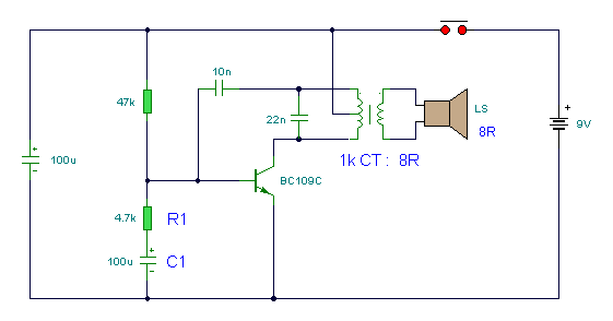
An 8-ohm speaker functions as both a microphone and an output device. The BC109C transistor operates in common base mode, providing substantial voltage gain while ensuring a low impedance input suitable for the speaker. Self DC biasing is implemented to...
Rain Sound Effects Generator
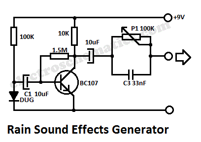
This rain sound effects generator circuit simulates the sound of rain and can be utilized in electronic music and radio shows. The noise source employs a germanium diode that is directly polarized and subsequently amplified by a single-stage amplifier to...