


TDA1524 Stereo Tone Control

Description: This simple tone control can be used in many audio applications. It can be added to amplifiers, used as a stand-alone control module, or even built into new and exciting instruments. Its one IC construction makes it a very compact circuit, as only a few support components are required. Plus, it does not use a dual power supply. More: This means that the circuit will run from VCC = 9V to 15V (although the bass will be a little weak at 9V). S1 is a contour control. Volume is controlled by P1. Balance is controlled by P2. P3 and P4 control bass and treble, respectively. J1 is the left.
This tone control circuit is designed to enhance audio signal processing in various applications, providing flexibility and ease of integration. The circuit utilizes a single integrated circuit (IC), which simplifies the design and minimizes the number of external components required, thus ensuring a compact layout suitable for both standalone modules and embedded applications in musical instruments.
The power supply for the circuit operates within a range of 9V to 15V. It is important to note that while the circuit is functional at 9V, the bass response may be diminished, indicating that optimal performance is achieved at higher voltages. This characteristic allows for versatility in different setups, accommodating a range of power supply options.
The control interface consists of several potentiometers and switches that allow users to manipulate the audio output. S1 functions as a contour control, enabling users to adjust the tonal characteristics of the audio signal. P1 is designated for volume control, providing a means to adjust the overall loudness of the output. P2 serves as a balance control, allowing for fine-tuning of the audio signal between left and right channels, which is critical in stereo applications.
Furthermore, P3 and P4 are dedicated to bass and treble adjustment, respectively. These controls enable users to tailor the audio output to their preferences, enhancing the listening experience by compensating for room acoustics or personal taste in sound. The left audio channel output is connected through J1, which is likely a jack or terminal for easy connectivity to other audio equipment.
Overall, this tone control circuit is a versatile solution for audio enhancement, suitable for a variety of applications, from home audio systems to professional musical instruments. Its compact design and straightforward controls make it an attractive option for audio engineers and hobbyists alike. This simple tone control can be used in may audio applications. It can be added to amplifers, used as a stand alone control module, or even built into new and exciting instruments. It's one IC construction makes it a very compact circuit, as only a few support components are required.
Plus, it does not use a dual power supply. This means that the circuit will run from VCC = 9V to 15V (although the bass will be a little weak at 9V). S1 is a contour control. Volume is controlled by P1. Balance is controlled by P2. P3 and P4 control bass and treble, respectivly. J1 is the left
This tone control circuit is designed to enhance audio signal processing in various applications, providing flexibility and ease of integration. The circuit utilizes a single integrated circuit (IC), which simplifies the design and minimizes the number of external components required, thus ensuring a compact layout suitable for both standalone modules and embedded applications in musical instruments.
The power supply for the circuit operates within a range of 9V to 15V. It is important to note that while the circuit is functional at 9V, the bass response may be diminished, indicating that optimal performance is achieved at higher voltages. This characteristic allows for versatility in different setups, accommodating a range of power supply options.
The control interface consists of several potentiometers and switches that allow users to manipulate the audio output. S1 functions as a contour control, enabling users to adjust the tonal characteristics of the audio signal. P1 is designated for volume control, providing a means to adjust the overall loudness of the output. P2 serves as a balance control, allowing for fine-tuning of the audio signal between left and right channels, which is critical in stereo applications.
Furthermore, P3 and P4 are dedicated to bass and treble adjustment, respectively. These controls enable users to tailor the audio output to their preferences, enhancing the listening experience by compensating for room acoustics or personal taste in sound. The left audio channel output is connected through J1, which is likely a jack or terminal for easy connectivity to other audio equipment.
Overall, this tone control circuit is a versatile solution for audio enhancement, suitable for a variety of applications, from home audio systems to professional musical instruments. Its compact design and straightforward controls make it an attractive option for audio engineers and hobbyists alike. This simple tone control can be used in may audio applications. It can be added to amplifers, used as a stand alone control module, or even built into new and exciting instruments. It's one IC construction makes it a very compact circuit, as only a few support components are required.
Plus, it does not use a dual power supply. This means that the circuit will run from VCC = 9V to 15V (although the bass will be a little weak at 9V). S1 is a contour control. Volume is controlled by P1. Balance is controlled by P2. P3 and P4 control bass and treble, respectivly. J1 is the left
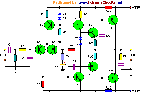
45 Watt Class-B Audio Power Amplifier
The goals were achieved by utilizing a discrete-component operational amplifier (op-amp) driving a bipolar junction transistor (BJT) complementary common-emitter output stage configured for Class B operation. In this configuration, the output transistors remain off for small output currents, allowing the...

Stereo Balance Meter Circuit
When the L and R signals are equal, no output is present from U1, and pin 6 is at a steady 4.5 V. Unbalanced audio causes the LEDs to vary in brightness, which indicates a difference that corresponds to the...

Amplifier circuit
An amplifier is a device that accepts a varying input signal and produces an output signal that varies in the same way as the input but has a larger amplitude. The input signal may be a current, voltage, mechanical motion,...

Hands-off-intercom
Amplifier A increases the microphone's output to a usable level. The output signal is fed to op amp B, which inverts the signal by 180 degrees. A balance-control potentiometer connects across the outputs of amplifiers A and B. If an...

UnDecima Audio Output from Arduino
There is a project involving an Arduino that outputs audio signals to USB speakers using 10-bit PWM. Initially, the sound quality produced via PWM was unsatisfactory due to the limited processing speed of the Arduino, which is insufficient for high-frequency...

TDA1521 / TDA1521Q: 12W Stereo Amplifier
This is a stereo audio amplifier circuit that delivers 12W output power for each audio channel. The circuit is constructed using a single integrated circuit, the TDA1521 or TDA1521Q, and is supported by a minimal number of external components.
The stereo...

Audio Millivoltmeter
An AC millivoltmeter - calibrated in dB - with a range of 30V down to 3mV full scale (80dB range) would be extremely useful. Attach a microphone (electret mic capsules are quite good), and you have a relative sound level...

KA9270 Audio Filter Introduction
KGA8010 is a broadband distributed amplifier utilizing 0.1 um-gate GaAs P-HEMT and coplanar waveguide technologies. The KGA8010 can serve as a multi-purpose amplifier for 40 Gb/s optical communication and millimeter wave applications. Manufactured by Oki Semiconductor.
The KGA8010 broadband distributed amplifier...

Three-channel tone control
The input signal is fed through SKI to the first active stage, which is constructed around IC1. This stage is configured as a non-inverting amplifier, with its gain determined by the ratio of R3 and R1. In this configuration, the...