


TDA1602A Application Circuit

Description: The A1602A is a 40-pin dual in-line package that functions as a playback preamplifier. It utilizes linear low-noise amplifiers with a voltage gain of 26.4 dB. Each channel has a separate discharge sound preamplifier, selected by an electronic switch that manages the sound balance network. The low corner frequency is determined by peripheral capacitance, particularly for Fe and Cr02, with a time constant of 120 µs controlled by a logic circuit. The circuit includes a high-speed recording head switch for rapid recording and a compensating capacitor connected to the input preamplifier. The head switch for the B-card recording head has two states: recording and playback. In recording mode, the preamplifier input terminal is grounded, and recording bias and signals are captured by the magnetic head. In playback mode, the recording bias current terminal is grounded. The left and right channel equalization network for audio conversion is determined by peripheral capacitors. These capacitors are omitted to ensure that the recorded sound balance network exhibits a flat response, meeting Dolby audio requirements. A biasing magnetic oscillator provides bias current for erasing tape recordings, with sinusoidal voltage amplitude controlled by the first 15 feet level. The biasing magnetic oscillator operates only in recording mode and automatically turns off otherwise. Automatic level control has a range of 20 dB, with output voltage variation of less than 2 dB. The ALC recovery time and rise time can be adjusted with external components. When using a single power supply, the reference voltage is set to 1/2 Vp as the signal ground. In dual power supply configurations, the reference voltage is at zero potential. The DC level of the internal logic circuit is controlled by an externally applied signal, with control signals on pins 0, 8, and 10 relevant for control levels. Control signals on pins 7 and 9 affect level transitions, allowing for smooth electronic switch operation.
The A1602A playback preamplifier circuit is designed with a focus on achieving high fidelity audio reproduction while maintaining low noise levels. The dual in-line package (DIP) configuration allows for easy integration into various electronic systems. The gain of 26.4 dB is optimized for typical audio applications, ensuring that the signal is amplified sufficiently for subsequent processing stages without introducing significant distortion.
The electronic switch that selects between the discharge sound preamplifiers plays a crucial role in maintaining sound balance across the left and right channels. This switch is controlled by a logic circuit that responds to user inputs or automatic adjustments, allowing for seamless transitions between playback and recording modes. The careful design of the audio equalization network ensures that both channels maintain a consistent frequency response, which is essential for high-quality audio playback, especially in applications adhering to Dolby standards.
The biasing magnetic oscillator is a vital component for recording operations, providing the necessary bias current for magnetic tape recording while also facilitating the erasure of previously recorded material. The oscillator's sinusoidal voltage control is particularly significant, as it allows for precise modulation of the recording signal, thus enhancing the overall recording quality.
Furthermore, the automatic level control (ALC) feature is designed to maintain consistent output levels regardless of input signal variations. This is particularly useful in dynamic audio environments where signal levels may fluctuate significantly. The ability to adjust recovery and rise times with external components adds flexibility to the design, allowing engineers to tailor the circuit's performance to specific applications or user preferences.
In terms of power supply configurations, the A1602A can operate effectively with either a single or dual power supply, providing versatility in system design. The reference voltage settings ensure that the circuit maintains proper signal grounding, which is critical for minimizing noise and ensuring stable operation.
Overall, the A1602A playback preamplifier circuit exemplifies a well-engineered solution for high-fidelity audio applications, combining advanced features with ease of integration and adaptability to various operational requirements.A1602A 40-pin dual in-line package, the circuit functions as follows: playback preamplifier is a linear low-noise amplifiers, voltage gain 26.4dBoA store cards, each with a sep arate discharge sound preamp, amp selected by the electronic switch sound balance network o left, high right twice been balanced network playback, low corner frequency is determined by the peripheral capacitance. Fe and Cr02 with the time constant 120ys Mu and controlled by the logic circuit. High-speed recording head switch for fast recording and the compensating capacitor connected to the Yasushi input preamplifier.
Head switch the B-card recording head has two states: the state of the recording and playback status. When recording status, the pre-amplifier input terminal is grounded, recording bias and recording signals recorded by the magnetic head.
When the playback mode, recording bias current terminal is grounded. Left, high and low frequency audio conversion right channel equalization network is determined by the periphery capacitors. These capacitors are omitted recorded sound balance network will show a flat response, in order to meet the requirements of the Dolby audio.
Biasing magnetic oscillator provides bias current and the erase tape recording. Sinusoidal voltage amplitude control by the first 15 foot level. Biasing magnetic oscillator only when the recording mode, it automatically turns o Automatic level control range of 20dB, the output voltage variation is less than 2dBoALC recovery time and rise time adjustment by the external components. When using a single power supply reference voltage 1/2 Vp potential as a signal ground. When using dual power supply, the reference voltage is zero potential. The DC level of the internal logic circuit by externally applied to control the electronic switch control signal contains 0 8,10 feet only relevant control level, control signal 7,9 feet not only level, but also on the level of control rise and fall between about so that the electronic switch can be a smooth transition.
The A1602A playback preamplifier circuit is designed with a focus on achieving high fidelity audio reproduction while maintaining low noise levels. The dual in-line package (DIP) configuration allows for easy integration into various electronic systems. The gain of 26.4 dB is optimized for typical audio applications, ensuring that the signal is amplified sufficiently for subsequent processing stages without introducing significant distortion.
The electronic switch that selects between the discharge sound preamplifiers plays a crucial role in maintaining sound balance across the left and right channels. This switch is controlled by a logic circuit that responds to user inputs or automatic adjustments, allowing for seamless transitions between playback and recording modes. The careful design of the audio equalization network ensures that both channels maintain a consistent frequency response, which is essential for high-quality audio playback, especially in applications adhering to Dolby standards.
The biasing magnetic oscillator is a vital component for recording operations, providing the necessary bias current for magnetic tape recording while also facilitating the erasure of previously recorded material. The oscillator's sinusoidal voltage control is particularly significant, as it allows for precise modulation of the recording signal, thus enhancing the overall recording quality.
Furthermore, the automatic level control (ALC) feature is designed to maintain consistent output levels regardless of input signal variations. This is particularly useful in dynamic audio environments where signal levels may fluctuate significantly. The ability to adjust recovery and rise times with external components adds flexibility to the design, allowing engineers to tailor the circuit's performance to specific applications or user preferences.
In terms of power supply configurations, the A1602A can operate effectively with either a single or dual power supply, providing versatility in system design. The reference voltage settings ensure that the circuit maintains proper signal grounding, which is critical for minimizing noise and ensuring stable operation.
Overall, the A1602A playback preamplifier circuit exemplifies a well-engineered solution for high-fidelity audio applications, combining advanced features with ease of integration and adaptability to various operational requirements.A1602A 40-pin dual in-line package, the circuit functions as follows: playback preamplifier is a linear low-noise amplifiers, voltage gain 26.4dBoA store cards, each with a sep arate discharge sound preamp, amp selected by the electronic switch sound balance network o left, high right twice been balanced network playback, low corner frequency is determined by the peripheral capacitance. Fe and Cr02 with the time constant 120ys Mu and controlled by the logic circuit. High-speed recording head switch for fast recording and the compensating capacitor connected to the Yasushi input preamplifier.
Head switch the B-card recording head has two states: the state of the recording and playback status. When recording status, the pre-amplifier input terminal is grounded, recording bias and recording signals recorded by the magnetic head.
When the playback mode, recording bias current terminal is grounded. Left, high and low frequency audio conversion right channel equalization network is determined by the periphery capacitors. These capacitors are omitted recorded sound balance network will show a flat response, in order to meet the requirements of the Dolby audio.
Biasing magnetic oscillator provides bias current and the erase tape recording. Sinusoidal voltage amplitude control by the first 15 foot level. Biasing magnetic oscillator only when the recording mode, it automatically turns o Automatic level control range of 20dB, the output voltage variation is less than 2dBoALC recovery time and rise time adjustment by the external components. When using a single power supply reference voltage 1/2 Vp potential as a signal ground. When using dual power supply, the reference voltage is zero potential. The DC level of the internal logic circuit by externally applied to control the electronic switch control signal contains 0 8,10 feet only relevant control level, control signal 7,9 feet not only level, but also on the level of control rise and fall between about so that the electronic switch can be a smooth transition.

audio preamplifier
Nowadays, audio signal preamplifiers are utilized in numerous electronic devices. There are various types of audio preamp circuits, ranging from simple to complex designs. This document presents an effective design of a compact signal preamplifier circuit, which is ideal for...

High-quality low-noise preamplifier
The circuit depicted in Figure 3-8 involves an input signal that passes through a low-pass filter before entering the differential amplifier. The composition of the FET (Field Effect Transistor) is evaluated at the preamplifier output. The differential amplifier connects to...

Scope-sensitivity-amplifier
This circuit provides a voltage gain of 20 ±0.1 dB from 0.5 to 25 MHz and ±3 dB from 70 kHz to 55 MHz. An LM733 video amplifier offers a low input noise specification, with a typical value of 10...

There are preamplifier with four inputs
Figure 3-25 illustrates a hybrid circuit featuring four input preamplifiers. The components C1, C2, C3, and C4 can accept signals from a microphone, line, phono, and crystal head respectively. The configuration allows for the individual or simultaneous entry of four...

Playback-preamplifier
The preamplifier is designed to offer a low-frequency boost at 50 Hz, maintain a flat response up to 3 kHz, and attenuate high frequencies above 3 kHz. Compensation for variations in tape and tape head performance can be accomplished by...
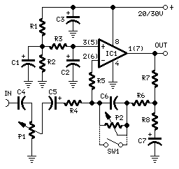
Stereo Preamplifier with Bass-boost
The preamplifier in question is engineered to interface with various audio devices such as CD players, tuners, and tape recorders. Its primary function is to provide an alternating current (AC) voltage gain of 4, an attribute that allows it to...
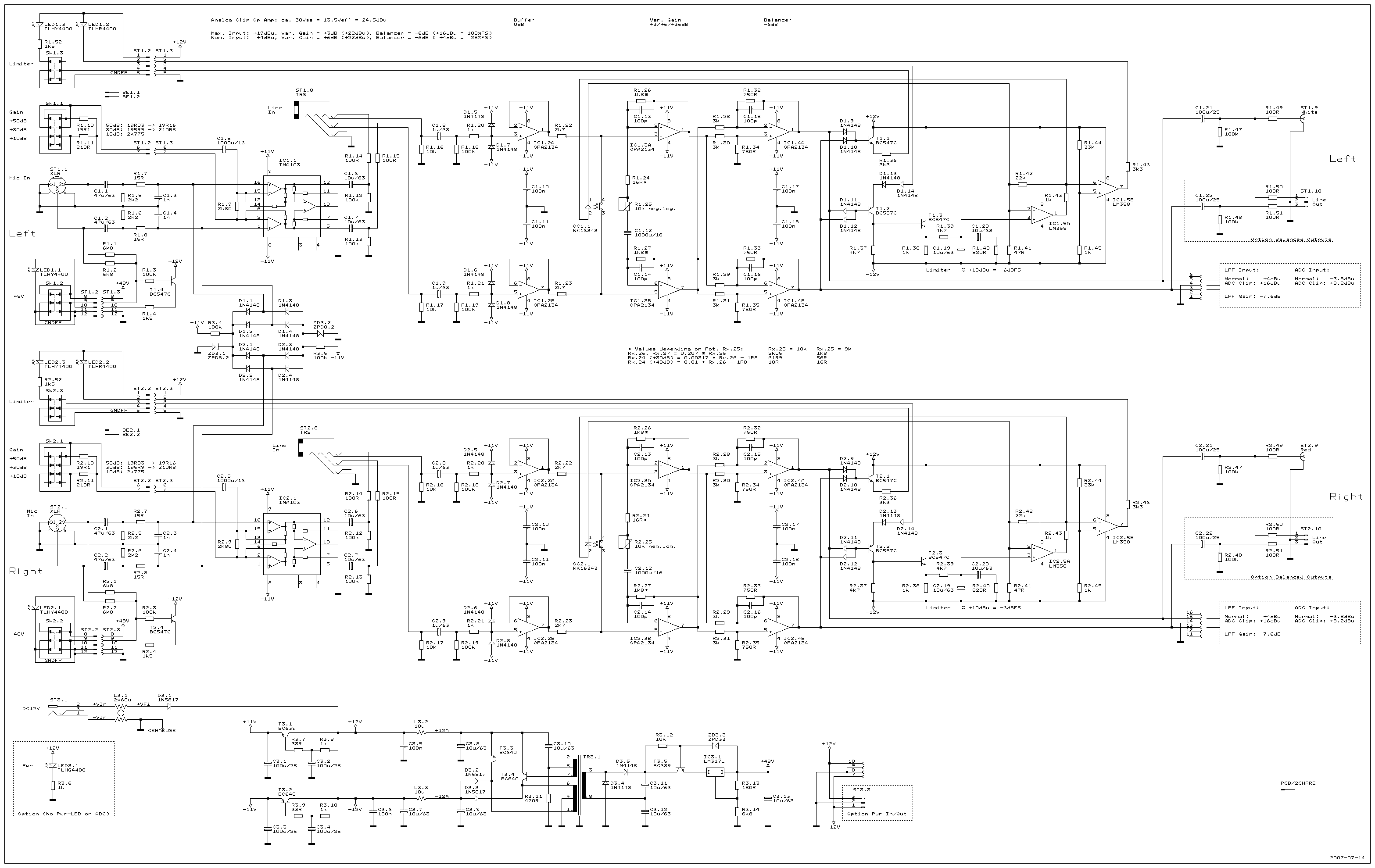
2ChPre
A dual-channel audio preamplifier designed to be an optimal preamplifier for the high-quality Audio Analog to Digital Converter AD24QS. The aim was not to create a smaller or cheaper preamplifier with similar functionality, but rather to develop a superior product....
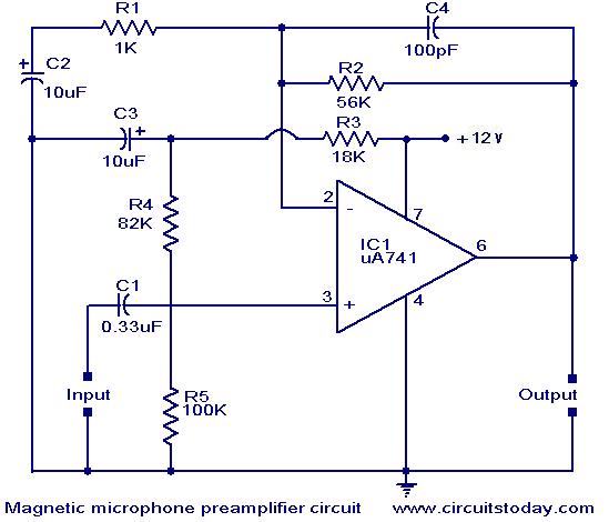
Magnetic pickup pre-amplifier circuit
A preamplifier for magnetic pickups of record players is presented. The uA 741 is utilized as an AC-coupled non-inverting amplifier operating on a single supply. The amplifier gain is determined by the feedback components, where C2 manages the low-frequency roll-off...

Magnetic-Pickup Phono Preamplifier
This is a simple circuit for a magnetic pickup phono preamplifier. The circuit provides appropriate loading to a reluctance. Here is the circuit: The gain...
The magnetic pickup phono preamplifier circuit is designed to amplify the low-level audio signals generated by...