


TDA2822 Audio Amplifier
#TDA2822
#audio amplifier
#SPI DAC
#microcontroller
#synthesizer
#waveforms
#optical link
#programmable

Description: The project is a variation of the popular POV toy, commonly seen as a beginner electronics project. This year, the decision was made to create a synthesizer kit, incorporating an SPI DAC, audio amplifier, microcontroller, and buttons. Additionally, there is a feature for programming new waveforms via an optical link to a computer. To provide a comprehensive overview, a detailed write-up will be conducted for each component of the project. The first component to examine is the audio amplifier, specifically the TDA2822M, which is a dual audio amplifier. Since the project does not require stereo channels, the TDA2822M will be configured in a bridge mode to enhance power delivery to the speaker. The schematic utilized is based on the TDA2822M datasheet and is designed to drive both sides of the speaker in mono for increased power output. It is crucial to consider the circuit's gain for future calculations, as the DAC output will range from approximately 0V to 5V. Voltage division will be necessary to prevent distortion and clipping. At a frequency of 1 kHz, the noted voltage gain is 39 dB, equivalent to a multiplication factor of around 89.125, which is significant. For prototyping, protoboard and soldering were chosen over breadboards to achieve a more efficient and durable design. After completing the soldering, the input of the TDA2822 audio amplifier was connected to a digital output of an Arduino, utilizing the tone function. The code used was derived from Arduino examples to test sound amplification through the speaker. Both available speakers performed adequately; however, a lower-cost speaker was selected to minimize expenses while maintaining functionality for sound experimentation and applications requiring a quality DAC.
The synthesizer kit utilizes an SPI DAC to convert digital signals into analog audio signals, which are then amplified by the TDA2822M audio amplifier. The TDA2822M is configured in a bridge mode to maximize power output, allowing for greater audio performance. This configuration effectively drives the speaker with higher efficiency, making it suitable for various audio applications.
The schematic for the TDA2822M includes connections for power supply, ground, input from the DAC, and output to the speaker. The gain of the amplifier must be carefully calculated to ensure that the output signal does not exceed the maximum voltage ratings, thereby preventing clipping and distortion. The gain setting can be adjusted based on the desired output levels, and it is essential to refer to the datasheet for precise values and configurations.
The microcontroller, likely an Arduino, serves as the central control unit for the synthesizer. The digital output from the Arduino is connected to the amplifier's input, enabling control over the audio signals. The tone function in the Arduino code generates specific frequencies that are sent to the amplifier, allowing for sound experimentation. The choice of using protoboard for assembly provides a robust platform for the components, ensuring reliability and ease of modifications during the development process.
In summary, this synthesizer kit represents an innovative approach to audio experimentation, combining a microcontroller, DAC, and audio amplifier in a compact and efficient design. The careful selection of components and configuration will facilitate a wide range of audio applications while maintaining cost-effectiveness.Usually the project is a variation on the POV toy, which you see around online all of the time as a beginner electronics project. However, we decided to deviate from our traditional path this year and create our own synthesizer kit, with an SPI DAC, Audio Amplifier, Microcontroller and some buttons.
There is also a possibility for programming in new wave forms via an optical link with a computer. To give a good overview of the whole project I plan on doing a write up on each part of the project as I go along. First up lets check the constraints of our Audio Amplifier and see if we can get it working in an appropriate way.
The amplifier we are using is a TDA2822M and is a dual audio amplifier. We are not driving a stereo channel, so we will be using the TDA2822M in a bridge configuration inorder to both push and pull on the speaker dramatically increasing the amount of power we can drive through the speaker. The datasheet for the TDA2822M is where the schematic above was pulled from. The schematic is a basic bridge, which drives both sides of the speaker in mono for added power. It is important to note the gain of the circuit for future calculations since the output of or DAC will be full swing from 0V to 5V (or close).
Thus we will need to divide those voltages so that we don`t clip everything to a funky looking square wave. At 1kHz the noted voltage gain is 39db, which is about Vin*89. 125. A rather respectable gain, which we will later have to contend with. I decided used to prototyping with breadboards, but this time I have decided to use protoboard and solder and skip breadboards completely.
While breadboards are nice I find that if I spend the time to sit down fully plan what I am doing and soldering it down on to protoboard that I reach an end result faster. Once the soldering was done (see schematic above), I hooked up the input of the TDA2822 Audio Amplifier to a digital output of an arduino and used the tone function.
The code that was used was straight from the Arduino examples. I just wanted to test that I could amplify sound and play it through the speaker. Both of the speakers I had available performed very well. However, the cost difference means that we should choose the lower cost speaker even though the sound quality is worse (but not by much). We want to minimise cost, while still providing a system which can be used to experiment with sound, or any application which requires a decent quality DAC.
/* Melody Plays a melody circuit: * 8-ohm speaker on digital pin 8 created 21 Jan 2010 modified 14 Oct 2010 by Tom Igoe This example code is in the public domain. */ #include "pitches. h" // notes in the melody: int melody[] = { NOTE_C4, NOTE_G3, NOTE_G3, NOTE_A3, NOTE_G3, 0, NOTE_B3, NOTE_C4}; // note durations: 4 = quarter note, 8 = eighth note, etc.
: int noteDurations[] = { 4, 8, 8, 4, 4, 4, 4, 4 }; void setup() { // iterate over the notes of the melody: for (int thisNote = 0; thisNote < 8; thisNote+) { // to calculate the note duration, take one second // divided by the note type. //e. g. quarter note = 1000 / 4, eighth note = 1000/8, etc. int noteDuration = 1000/noteDurations[thisNote]; tone(8, melody[thisNote], noteDuration); // to distinguish the notes, set a minimum time between them.
// the note`s duration + 30% seems to work well: int pauseBetweenNotes = noteDuration * 1. 30; delay(pauseBetweenNotes); // stop the tone playing: noTone(8); } } void loop() { // no need to repeat the melody. }
The synthesizer kit utilizes an SPI DAC to convert digital signals into analog audio signals, which are then amplified by the TDA2822M audio amplifier. The TDA2822M is configured in a bridge mode to maximize power output, allowing for greater audio performance. This configuration effectively drives the speaker with higher efficiency, making it suitable for various audio applications.
The schematic for the TDA2822M includes connections for power supply, ground, input from the DAC, and output to the speaker. The gain of the amplifier must be carefully calculated to ensure that the output signal does not exceed the maximum voltage ratings, thereby preventing clipping and distortion. The gain setting can be adjusted based on the desired output levels, and it is essential to refer to the datasheet for precise values and configurations.
The microcontroller, likely an Arduino, serves as the central control unit for the synthesizer. The digital output from the Arduino is connected to the amplifier's input, enabling control over the audio signals. The tone function in the Arduino code generates specific frequencies that are sent to the amplifier, allowing for sound experimentation. The choice of using protoboard for assembly provides a robust platform for the components, ensuring reliability and ease of modifications during the development process.
In summary, this synthesizer kit represents an innovative approach to audio experimentation, combining a microcontroller, DAC, and audio amplifier in a compact and efficient design. The careful selection of components and configuration will facilitate a wide range of audio applications while maintaining cost-effectiveness.Usually the project is a variation on the POV toy, which you see around online all of the time as a beginner electronics project. However, we decided to deviate from our traditional path this year and create our own synthesizer kit, with an SPI DAC, Audio Amplifier, Microcontroller and some buttons.
There is also a possibility for programming in new wave forms via an optical link with a computer. To give a good overview of the whole project I plan on doing a write up on each part of the project as I go along. First up lets check the constraints of our Audio Amplifier and see if we can get it working in an appropriate way.
The amplifier we are using is a TDA2822M and is a dual audio amplifier. We are not driving a stereo channel, so we will be using the TDA2822M in a bridge configuration inorder to both push and pull on the speaker dramatically increasing the amount of power we can drive through the speaker. The datasheet for the TDA2822M is where the schematic above was pulled from. The schematic is a basic bridge, which drives both sides of the speaker in mono for added power. It is important to note the gain of the circuit for future calculations since the output of or DAC will be full swing from 0V to 5V (or close).
Thus we will need to divide those voltages so that we don`t clip everything to a funky looking square wave. At 1kHz the noted voltage gain is 39db, which is about Vin*89. 125. A rather respectable gain, which we will later have to contend with. I decided used to prototyping with breadboards, but this time I have decided to use protoboard and solder and skip breadboards completely.
While breadboards are nice I find that if I spend the time to sit down fully plan what I am doing and soldering it down on to protoboard that I reach an end result faster. Once the soldering was done (see schematic above), I hooked up the input of the TDA2822 Audio Amplifier to a digital output of an arduino and used the tone function.
The code that was used was straight from the Arduino examples. I just wanted to test that I could amplify sound and play it through the speaker. Both of the speakers I had available performed very well. However, the cost difference means that we should choose the lower cost speaker even though the sound quality is worse (but not by much). We want to minimise cost, while still providing a system which can be used to experiment with sound, or any application which requires a decent quality DAC.
/* Melody Plays a melody circuit: * 8-ohm speaker on digital pin 8 created 21 Jan 2010 modified 14 Oct 2010 by Tom Igoe This example code is in the public domain. */ #include "pitches. h" // notes in the melody: int melody[] = { NOTE_C4, NOTE_G3, NOTE_G3, NOTE_A3, NOTE_G3, 0, NOTE_B3, NOTE_C4}; // note durations: 4 = quarter note, 8 = eighth note, etc.
: int noteDurations[] = { 4, 8, 8, 4, 4, 4, 4, 4 }; void setup() { // iterate over the notes of the melody: for (int thisNote = 0; thisNote < 8; thisNote+) { // to calculate the note duration, take one second // divided by the note type. //e. g. quarter note = 1000 / 4, eighth note = 1000/8, etc. int noteDuration = 1000/noteDurations[thisNote]; tone(8, melody[thisNote], noteDuration); // to distinguish the notes, set a minimum time between them.
// the note`s duration + 30% seems to work well: int pauseBetweenNotes = noteDuration * 1. 30; delay(pauseBetweenNotes); // stop the tone playing: noTone(8); } } void loop() { // no need to repeat the melody. }

20W audio amplifier using TDA7240
The audio amplifier presented here is based on the TDA7240 integrated circuit from ST Microelectronics. The TDA7240 is capable of delivering 20 watts of audio output power into a 4-ohm load. It requires a minimal number of external components and...

Class B audio amplifier Analog Integrated Circuits
This project is an audio amplifier designed to amplify output signals from small radios, tape players, CD players, or other audio signal sources. For stereo operation, two identical amplifiers must be constructed—one for the left channel and another for the...

Bridged amplifier circuit diagram of LM4065
A 750mW bridge-tied load audio amplifier circuit utilizing the LM4065 amplifier is presented below. The LM4865 is available in an 8-pin SO package and an 8-pin mini SMD package. The power supply voltage (VDD) ranges from 2.7V to 5.5V, with...

10W Audio Amplifier with Bass-boost
This design is based on an 18 Watt audio amplifier and was developed primarily to meet the needs of users who are unable to find the TLE2141C chip. It utilizes the widely available NE5532 dual integrated circuit; however, its power...

1W Stereo Headphone Amplifier based TDA2822 circuit diagram
A 1W stereo headphone amplifier circuit, based on the TDA2822, is designed for portable players, radios, and other electronic devices that utilize headphones as the output.
The TDA2822 is a dual audio power amplifier IC capable of delivering up to 1W...

Four channel synthesizer
This circuit synthesizes two rear channels for quadraphonic sound when provided with a stereo signal. The rear output for the left channel is created by combining the left channel input, which is 180 degrees out of phase, with a portion...
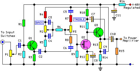
30 Watt Audio Power Amplifier
This project involved the design of an audio amplifier capable of delivering substantial output power with minimal component count while maintaining high quality. The power amplifier section utilizes three transistors along with a few resistors and capacitors in a shunt...

25 Watt Audio Amplifier Circuit
This is a 25 Watt basic power amplifier designed to be relatively easy to build at a reasonable cost. It offers better performance than the standard STK module amplifiers commonly used in nearly all mass-market stereo receivers manufactured today.
The 25...

8 watts audio amplifier circuit
What value of potentiometer should be used for the volume control of this audio amplifier circuit, and where should it be connected? Thank you.
In audio amplifier circuits, the choice of potentiometer value for volume control is crucial for achieving optimal...