


three channel audio splitter
#audio splitter
#amplifier
#audio distribution
#buffered output
#impedance matching
#IC1
#J1 connector
#P1 potentiometer
#multi-channel audio
#signal redistribution

Description: This circuit is designed to amplify and distribute audio signals. The input audio signal is connected to J1 and, after passing through P1, it is buffered and amplified by IC1 for redistribution. It features three outputs that can drive three audio lines with an impedance of 300 ohms.
The circuit operates by first receiving the audio signal at connector J1, which serves as the input interface. The signal then travels through potentiometer P1, allowing for adjustable gain control. This component is crucial for fine-tuning the amplitude of the audio signal before it reaches the amplifier stage.
Following the potentiometer, the signal is directed to integrated circuit IC1, which functions as the main amplification unit. This IC is selected for its ability to provide high fidelity amplification while maintaining low distortion levels. The output from IC1 is split into three separate paths, enabling the circuit to drive multiple audio lines simultaneously. Each output is designed to maintain a consistent impedance of 300 ohms, ensuring compatibility with standard audio equipment and minimizing signal loss.
The circuit may also include bypass capacitors and filtering components to eliminate noise and enhance the overall audio quality. The layout should be carefully designed to minimize interference and ensure stable operation across various audio frequencies. Proper grounding and shielding practices should be implemented to further improve performance and reliability in real-world applications.This circuit is suitable to amplify and distribute the audio signals. The input audio signal is applied to the J1 and after passing through the P1, It is buffered and amplified by the IC1 prepared to redistribute. It has 3 outputs to drive 3 audio lines with 300 ohms impedance..
The circuit operates by first receiving the audio signal at connector J1, which serves as the input interface. The signal then travels through potentiometer P1, allowing for adjustable gain control. This component is crucial for fine-tuning the amplitude of the audio signal before it reaches the amplifier stage.
Following the potentiometer, the signal is directed to integrated circuit IC1, which functions as the main amplification unit. This IC is selected for its ability to provide high fidelity amplification while maintaining low distortion levels. The output from IC1 is split into three separate paths, enabling the circuit to drive multiple audio lines simultaneously. Each output is designed to maintain a consistent impedance of 300 ohms, ensuring compatibility with standard audio equipment and minimizing signal loss.
The circuit may also include bypass capacitors and filtering components to eliminate noise and enhance the overall audio quality. The layout should be carefully designed to minimize interference and ensure stable operation across various audio frequencies. Proper grounding and shielding practices should be implemented to further improve performance and reliability in real-world applications.This circuit is suitable to amplify and distribute the audio signals. The input audio signal is applied to the J1 and after passing through the P1, It is buffered and amplified by the IC1 prepared to redistribute. It has 3 outputs to drive 3 audio lines with 300 ohms impedance..

Active-limiting-amplifier
The modified inverting amplifier employs an active clamp to precisely limit the output swing. Consideration must be given to the VBE of the transistors. The output swing is restricted by the base-emitter breakdown of the transistors. A straightforward circuit configuration...

A simple and effective short-wave antenna amplifier circuit
This amplifier is designed for outdoor installation and is connected to an indoor power line box. It utilizes either 50-ohm or 75-ohm coaxial cables for the connection between indoor and outdoor units. The amplifier circuit board is depicted in Figures...

Amplifier Timer Circuit Schematic
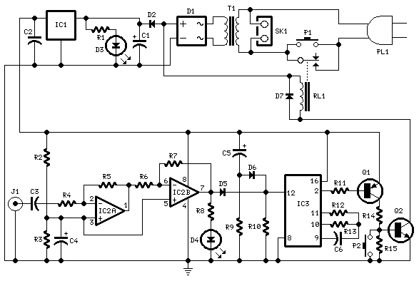
This circuit deactivates an amplifier or any connected device when a low-level audio signal is absent at its input for at least 15 minutes. Activating switch P1 powers the device, enabling operation of any appliance connected to SK1. The input...

Amplifier Timer Circuit Schematic
This circuit turns off an amplifier or any other device when a low-level audio signal fed to its input is absent for at least 15 minutes. Pressing P1 switches the device on, supplying power to any appliance connected to SK1....

Self Oscillating Amplifier for Distortion Testing
The circuit is based on a simple inductor-capacitor filter circuit, and needs only a pot and a small light bulb to set and stabilise the oscillation. The frequency is fixed, and with a good inductor should be capable of very...
Amplifier Timer
This circuit deactivates an amplifier or other devices when a low-level audio signal at its input is absent for at least 15 minutes. By pressing P1, the device is activated, supplying power to any appliance connected to SK1. The input...

headphone monitor amp
This simple amplifier is designed to add a headphone jack to equipment that does not have this feature. The Headphone Buffer circuit board is compact (1.2" x 1.4"), allowing it to fit into even the smallest spaces, and its low...

RECEIVER BUILDING BLOCKS
This amplifier has about 20dB of gain, bandwidth of 100MHz and noise figure of about 7dB. The output transformer is 8 turns bifilar wound on a ferrite core. Use a medium power UHF transistor 2N5109, 2N3866, 2N4427 or similar. The...

Broadband high frequency amplifying circuit
A broadband high-frequency amplifying circuit is primarily composed of a high-frequency matching transformer and an amplifying transistor. This circuit is designed to handle large high-frequency signals. The input of the amplifier circuit utilizes a matching transformer to ensure that the...