


Tone detector / Sound Activated switch
#tone detector
#sound activated switch
#microphone
#NE567
#opamp
#amplifier
#sensitivity
#feedback resistor
#1458 opamp

Description: The detector is a bit more complex. It amplifies a microphone and sends the resulting signal to an NE567 tone decoder. The amplifier is half of a 1458 opamp. The two 120K resistors attached to pin 3 keep the opamp's average output at about halfway between the 5 vdc source and ground. These resistor values are non-critical, but should be equal. The 120K feedback resistor from pin 1 to 2 establishes the gain of the amplifier and the sensitivity of the detector to a generated tone. It was found that 120K provided reliable operation with the generator about 3 feet from the microphone. This resistor can be varied to make the detector more or less sensitive. More resistance increases sensitivity. The two 0.01 uf capacitors eliminate DC voltages, and their values are non-critical.
The 567 works by comparing the input signal to an internal oscillator whose frequency is determined by the 25K variable resistor and the 0.022 uf capacitor. These components can be varied as necessary to match the oscillator frequency to the tone generator. A 10 turn pot for the 25K resistor was used, yielding a resistance of about 11K to match the tone generator. The 567 requires a close frequency match to trigger, with the output going low when the frequencies align. Occasional readjustment of the 25K resistor may be necessary for reliable operation, and making this adjustment accessible is advisable in packaged circuits.
The 20K pull-up resistor on the output can be modified or removed to suit processor requirements. The 1uF and 0.1uF capacitors provide filtering and bandwidth adjustment; reference application notes for further adjustments.
Data on the NE567 can be found at http://www-us6.semiconductors.com/pip/ne567d (or if this link becomes obsolete, search for "Phillips Semiconductors").
The 1458 is available at Radio Shack and many other sources.
The circuit described utilizes a standard operational amplifier (op-amp) configuration to amplify an audio signal captured by a microphone. The NE567 tone decoder is employed for frequency detection, enabling the system to respond to specific audio tones.
The op-amp, configured as a non-inverting amplifier, uses the feedback resistor (120K) to determine gain, allowing adjustment of sensitivity to the incoming audio signal. The two 120K resistors connected to the non-inverting input (pin 3) ensure that the output voltage is centered at half the supply voltage, which is crucial for proper amplification without distortion.
The NE567 tone decoder operates by comparing the amplified audio signal against an internally generated frequency, which is adjustable via the 25K variable resistor and the 0.022uF capacitor. This setup allows for fine-tuning to ensure the decoder responds accurately to the desired tone frequency. The close matching of frequencies is critical for the decoder's output to transition low, indicating a successful tone detection.
Capacitors in the circuit, such as the 0.01uF capacitors, serve to block any DC offset from affecting the performance of the amplifier and the tone decoder. Additionally, the 1uF and 0.1uF capacitors provide further filtering, which can be adjusted based on the application requirements.
The output stage includes a 20K pull-up resistor, which can be tailored to the needs of the connected microcontroller or processing unit. This flexibility allows integration with various digital systems, enhancing the adaptability of the circuit design.
In summary, this circuit design effectively amplifies audio signals and detects specific tones, making it suitable for a range of applications, including audio processing and signal detection in embedded systems. Proper component selection and adjustment are essential for optimal performance.The detector (below) is a bit more complex. It amplifies a microphone and sends the resulting signal to an NE567 tone decoder. The amplifier is half of a 1458 opamp. The two 120K resistors attached to pin 3 keep the opamp's average output at about halfway between the 5 vdc source and ground. These resistor values are non-critical, but should be equal. The 120K feedback resistor from pin 1 to 2 establishes the gain of the amplifier and the sensitivity of the detector to a generated tone.
I found that 120K gave me pretty reliable operation at about with the generator about 3 feet from the microphone. You can vary this resistor to make the detector more or less sensitive if you wish. More resistance makes it more sensitive. The two 0.01 uf capacitors are just to eliminate dc voltages. Their values are non-critical. The 567 works by comparing the input signal to an internal oscillator whose frequency is determined by the 25K variable resistor and the 0.022 uf capacitor. You vary these components as necessary to get the oscillator at the same frequency as your tone generator.
I used a 10 turn pot for the 25K which worked fine. The resulting resistance to match my tone generator was about 11K. The 567 requires a pretty close frequency match to trip (the output goes low when the frequencies match). I find that I occasionally have to readjust the 25K resistor to get a reliable trip. You might want to make this adjustment accessible if you package the circuit. The 20K pullup resistor on the output can be changed or deleted to match your processor's requirements.
The 1uf and 0.1uf capacitors provide some filtering and bandwidth adjustment. See the application notes if you want to adjust them. Data on the NE567 can be found at http://www-us6.semiconductors.com/pip/ne567d (or if this link becomes obsolete, search for "Phillips Semiconductors") The 1458 is available at Radio Shack and many other sources..
The 567 works by comparing the input signal to an internal oscillator whose frequency is determined by the 25K variable resistor and the 0.022 uf capacitor. These components can be varied as necessary to match the oscillator frequency to the tone generator. A 10 turn pot for the 25K resistor was used, yielding a resistance of about 11K to match the tone generator. The 567 requires a close frequency match to trigger, with the output going low when the frequencies align. Occasional readjustment of the 25K resistor may be necessary for reliable operation, and making this adjustment accessible is advisable in packaged circuits.
The 20K pull-up resistor on the output can be modified or removed to suit processor requirements. The 1uF and 0.1uF capacitors provide filtering and bandwidth adjustment; reference application notes for further adjustments.
Data on the NE567 can be found at http://www-us6.semiconductors.com/pip/ne567d (or if this link becomes obsolete, search for "Phillips Semiconductors").
The 1458 is available at Radio Shack and many other sources.
The circuit described utilizes a standard operational amplifier (op-amp) configuration to amplify an audio signal captured by a microphone. The NE567 tone decoder is employed for frequency detection, enabling the system to respond to specific audio tones.
The op-amp, configured as a non-inverting amplifier, uses the feedback resistor (120K) to determine gain, allowing adjustment of sensitivity to the incoming audio signal. The two 120K resistors connected to the non-inverting input (pin 3) ensure that the output voltage is centered at half the supply voltage, which is crucial for proper amplification without distortion.
The NE567 tone decoder operates by comparing the amplified audio signal against an internally generated frequency, which is adjustable via the 25K variable resistor and the 0.022uF capacitor. This setup allows for fine-tuning to ensure the decoder responds accurately to the desired tone frequency. The close matching of frequencies is critical for the decoder's output to transition low, indicating a successful tone detection.
Capacitors in the circuit, such as the 0.01uF capacitors, serve to block any DC offset from affecting the performance of the amplifier and the tone decoder. Additionally, the 1uF and 0.1uF capacitors provide further filtering, which can be adjusted based on the application requirements.
The output stage includes a 20K pull-up resistor, which can be tailored to the needs of the connected microcontroller or processing unit. This flexibility allows integration with various digital systems, enhancing the adaptability of the circuit design.
In summary, this circuit design effectively amplifies audio signals and detects specific tones, making it suitable for a range of applications, including audio processing and signal detection in embedded systems. Proper component selection and adjustment are essential for optimal performance.The detector (below) is a bit more complex. It amplifies a microphone and sends the resulting signal to an NE567 tone decoder. The amplifier is half of a 1458 opamp. The two 120K resistors attached to pin 3 keep the opamp's average output at about halfway between the 5 vdc source and ground. These resistor values are non-critical, but should be equal. The 120K feedback resistor from pin 1 to 2 establishes the gain of the amplifier and the sensitivity of the detector to a generated tone.
I found that 120K gave me pretty reliable operation at about with the generator about 3 feet from the microphone. You can vary this resistor to make the detector more or less sensitive if you wish. More resistance makes it more sensitive. The two 0.01 uf capacitors are just to eliminate dc voltages. Their values are non-critical. The 567 works by comparing the input signal to an internal oscillator whose frequency is determined by the 25K variable resistor and the 0.022 uf capacitor. You vary these components as necessary to get the oscillator at the same frequency as your tone generator.
I used a 10 turn pot for the 25K which worked fine. The resulting resistance to match my tone generator was about 11K. The 567 requires a pretty close frequency match to trip (the output goes low when the frequencies match). I find that I occasionally have to readjust the 25K resistor to get a reliable trip. You might want to make this adjustment accessible if you package the circuit. The 20K pullup resistor on the output can be changed or deleted to match your processor's requirements.
The 1uf and 0.1uf capacitors provide some filtering and bandwidth adjustment. See the application notes if you want to adjust them. Data on the NE567 can be found at http://www-us6.semiconductors.com/pip/ne567d (or if this link becomes obsolete, search for "Phillips Semiconductors") The 1458 is available at Radio Shack and many other sources..

Car Antenna Amplifier Circuit
The total gain of the car antenna amplifier is approximately 30 dB, with an input impedance of around 10 kΩ at 30 MHz. The amplifier should be mounted directly at the base of the antenna to prevent signal losses attributed...

microphone Neumann UM 57
The Neumann/Gefell UM 57 is a large-diaphragm tube condenser microphone produced by the Neumann company in Gefell, Germany, now known as Microtech-Gefell. This microphone features the renowned M7 capsule from Gefell, which is a dual-diaphragm, center-terminated design with a PVC...

microphone computer circuit schematic
The sound card for a PC typically includes a microphone input, speaker output, and occasionally line inputs and outputs. The microphone input is specifically designed for dynamic microphones with an impedance range of 200 to 600 ohms. An adaptation has...

Build a Microphone Polarity Tester
Many things can go wrong in a modern recording studio, but few are as difficult to track down as reversed microphone polarity. When a microphone is placed in front of a sound source, a positive pressure on its diaphragm caused...

Computer microphone circuit diagram
The sound card for a PC typically includes a microphone input, speaker output, and occasionally line inputs and outputs. The microphone input is specifically designed for dynamic microphones, accommodating an impedance range of 200 to 600 ohms. An adaptation has...
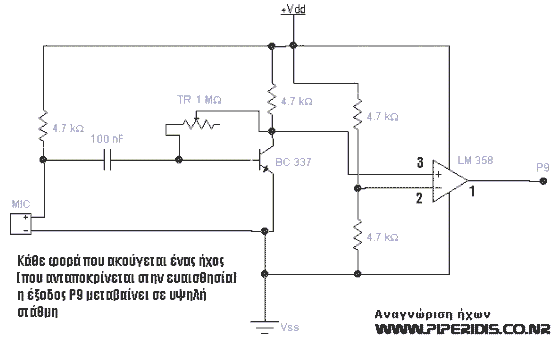
Microphone Amp
This circuit is designed to detect sounds using a common condenser microphone, with variable sensitivity. The output of the circuit is high whenever a sound is detected and low otherwise. It can be utilized in simple robotic applications for sound...

Using the Panasonic WM61A as a Measurement Microphone
Measurement microphones differ from recording microphones and sound meters; they have a flat response (usually well below 20 Hz and above 20 kHz) and do not have a "weighted" or equalized frequency response. They are optimized for measuring high SPL...

A simple and effective short-wave antenna amplifier circuit
This amplifier is designed for outdoor installation and is connected to an indoor power line box. It utilizes either 50-ohm or 75-ohm coaxial cables for the connection between indoor and outdoor units. The amplifier circuit board is depicted in Figures...

1.5V-powered microphone signal amplifying circuit
A 1.5V-powered microphone signal amplifying circuit is designed with a power supply for the microphone signal amplification. The circuit primarily consists of a differential amplifier formed by transistors VT2 and VT3. Additionally, VT6 functions as a common emitter voltage amplifier,...