


TV audio circuit diagram TA8218AH
#TA8218AH
#television
#audio amplifier
#stereo
#sound system
#audio circuit
#R-channel
#L-channel
#reference voltage
#inverting input

Description: The audio circuit depicted in the figure is commonly utilized in color television systems. The pin functions and reference voltages for the TA8218AH are as follows: Pin 1: 1.9V - inverting input; Pin 2: 2.1V - R-channel audio signal input terminal; Pin 3: 0V - ground; Pin 4: 1.9V - inverting input; Pin 5: 2.1V - bass audio signal input terminal; Pin 6: 2.1V - L-channel audio signal input; Pin 7: 1.9V - inverting input; Pin 8: 8.9V - filter; Pin 9: 26V - power supply; Pin 10: 13V - L-channel audio signal output; Pin 11: 4.7V - mute; Pin 12: 4.5V - unused; Pin 13: 0V - ground; Pin 14: 13V - bass signal output; Pin 15: 5.0V - unused; Pin 16: 4.6V - mute; Pin 17: 13V - R-channel audio signal output.
The TA8218AH is an integrated audio amplifier used primarily in color television sets, designed to enhance audio performance by providing both left and right channel outputs along with additional functionalities like bass signal processing and mute control. The pin configuration plays a crucial role in the overall operation of the circuit.
The inverting inputs on pins 1, 4, and 7 are essential for signal processing, allowing the amplifier to effectively manage audio signals from various sources. The R-channel and L-channel audio signal input terminals (pins 2 and 6) facilitate the input of audio from the television's audio source. The bass audio signal input on pin 5 is specifically tailored to enhance low-frequency sounds, contributing to an improved audio experience.
Ground connections are established through pins 3 and 13, ensuring a stable reference point for the circuit, which is necessary for proper operation and noise reduction. The power supply pin (pin 9) is critical for the amplifier's functionality, providing the necessary voltage to drive the circuit. The outputs for the left and right channels are found on pins 10 and 17, respectively, delivering the amplified audio signal to the speakers.
The mute functionality is accessible through pins 11 and 16, which can be employed to silence the audio output as needed. Additionally, the unused pins (12 and 15) may be reserved for future enhancements or specific applications, allowing flexibility in design. The filter pin (pin 8) plays a role in signal processing, ensuring that the output audio is clear and free from unwanted noise.
Overall, the TA8218AH audio circuit is a sophisticated solution for audio amplification in color televisions, with a well-defined pin layout that supports various audio processing capabilities. As shown in FIG audio circuit is commonly used in color television, TA8218AH pin functions and reference voltage: Pin 1: 1.9V-- inverting input Pin 2: 2.1V - R-channel audio si gnal input terminal Pin 3: 0V-- ground 4 feet: 1.9V-- inverting input 5 feet: 2.1V-- bass audio signal input terminal Pin 6: 2.1V - L-channel audio signal input Pin 7: 1.9V-- inverting input 8 feet: 8.9V-- filter 9-pin: 26V-- Power 10 feet: 13V - L-channel audio signal output 11 feet: 4.7V-- Mute 12 feet: 4.5V-- empty 13 feet: 0V-- ground 14 feet: 13V-- bass signal output 15 feet: 5.0V-- empty 16 feet: 4.6V-- Mute 17 feet: 13V - R-channel audio signal output
The TA8218AH is an integrated audio amplifier used primarily in color television sets, designed to enhance audio performance by providing both left and right channel outputs along with additional functionalities like bass signal processing and mute control. The pin configuration plays a crucial role in the overall operation of the circuit.
The inverting inputs on pins 1, 4, and 7 are essential for signal processing, allowing the amplifier to effectively manage audio signals from various sources. The R-channel and L-channel audio signal input terminals (pins 2 and 6) facilitate the input of audio from the television's audio source. The bass audio signal input on pin 5 is specifically tailored to enhance low-frequency sounds, contributing to an improved audio experience.
Ground connections are established through pins 3 and 13, ensuring a stable reference point for the circuit, which is necessary for proper operation and noise reduction. The power supply pin (pin 9) is critical for the amplifier's functionality, providing the necessary voltage to drive the circuit. The outputs for the left and right channels are found on pins 10 and 17, respectively, delivering the amplified audio signal to the speakers.
The mute functionality is accessible through pins 11 and 16, which can be employed to silence the audio output as needed. Additionally, the unused pins (12 and 15) may be reserved for future enhancements or specific applications, allowing flexibility in design. The filter pin (pin 8) plays a role in signal processing, ensuring that the output audio is clear and free from unwanted noise.
Overall, the TA8218AH audio circuit is a sophisticated solution for audio amplification in color televisions, with a well-defined pin layout that supports various audio processing capabilities. As shown in FIG audio circuit is commonly used in color television, TA8218AH pin functions and reference voltage: Pin 1: 1.9V-- inverting input Pin 2: 2.1V - R-channel audio si gnal input terminal Pin 3: 0V-- ground 4 feet: 1.9V-- inverting input 5 feet: 2.1V-- bass audio signal input terminal Pin 6: 2.1V - L-channel audio signal input Pin 7: 1.9V-- inverting input 8 feet: 8.9V-- filter 9-pin: 26V-- Power 10 feet: 13V - L-channel audio signal output 11 feet: 4.7V-- Mute 12 feet: 4.5V-- empty 13 feet: 0V-- ground 14 feet: 13V-- bass signal output 15 feet: 5.0V-- empty 16 feet: 4.6V-- Mute 17 feet: 13V - R-channel audio signal output
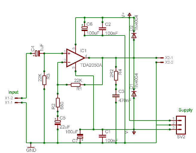
3-channel Audio Amplifier circuit
A careful examination of the amplifier photos reveals that the heatsink on the HY60 near-clone built using the TDA2050A is slightly shorter than that of the original HY60s. This unit is positioned at the rear of the amplifier, creating a...

10 vpp audio amplifier circuit
A simple audio amplifier with a 10 Vpp output designed for use with the AD633 ring modulation chip. The datasheet for the chip is available, and the circuit will utilize the XR2206 function generator IC for the modulation input.
The...

Circuit of power audio amplifier lm1875 20W
The LM1875 is a monolithic audio amplifier that provides very low distortion and high-quality performance for audio amplifier projects. The LM1875 delivers 20 watts into loads of 4 Ohms or 8 Ohms.
The LM1875 audio amplifier is designed for applications requiring...

8 watts audio amplifier circuit
What value of potentiometer should be used for the volume control of this audio amplifier circuit, and where should it be connected? Thank you.
In audio amplifier circuits, the choice of potentiometer value for volume control is crucial for achieving optimal...

200 Watt High Quality Audio Amplifier
This high-power audio amplifier provides top-quality performance for loudspeakers with an impedance of 4 to 8 ohms. It operates within a frequency range of 20 to 20,000 Hz and requires a voltage supply of 24 to 36 volts, with a...

BA3822 five-point stereo graphic equalizer circuit design
The BA3822 is a five-point stereo graphic equalizer integrated circuit that operates with two channels. Each channel can independently set five center frequencies using external capacitors. This integrated circuit supports a wide operating power supply voltage range (VCC = 3.5V...

TDA8340 Television If Amplifier And Demodulator - Nxp Semiconductors
The TDA9813T is an integrated circuit designed for processing vision intermediate frequency (IF) signals and dual frequency modulation (FM) demodulation of sound. It operates with a single reference QSS-IF in television (TV) and video cassette recorder (VCR) applications, specifically supporting...

General-Purpose 5W Audio Amplifier With Ac Power Supply
This general-purpose low-power (5 W) audio amplifier is designed to drive speakers ranging from 8 to 12 inches. It utilizes a Sanyo LA4460 integrated circuit (IC) as the audio output component. The circuit features a loudness control, a driver amplifier...

Stereo OTL Audio Amplifier
The following diagram illustrates the circuit of a Stereo OTL Audio Amplifier. It is based on an integrated circuit (IC), making the circuit design straightforward. The amplifier project can utilize ICs such as LM379, LM377, or LM378. According to the...