


TV audio circuit TDA2009
#TDA2009
#television
#audio amplifier
#left channel
#feedback
#squelch
#stereo
#sound system
#audio processing
#TV circuit

Description: The audio circuit, commonly utilized in color television sets, features the TDA2009 integrated circuit. The pin configuration is as follows: Pin 1 is designated for the left channel input at 1.2V, Pin 2 serves as the left channel feedback at 0.8V, Pin 3 is for Squelch at 12V, Pin 4 is for right channel feedback at 0.8V, Pin 5 is the right channel input at 1.2V, Pin 6 is connected to ground at 0V, Pin 7 is empty at 0V, Pin 8 provides the right channel output at 12.4V, Pin 9 is the power supply at 24V, and Pin 10 is the left channel output at 12.4V.
The TDA2009 is a popular audio amplifier IC used in various applications, particularly in color television sets. This device is designed to deliver high-quality audio output while maintaining low distortion levels. The pin configuration described allows for efficient signal processing and amplification of audio signals from both left and right channels.
Pin 1, with a voltage of 1.2V, receives the audio input for the left channel, which is then processed through the amplifier. Pin 2, at 0.8V, functions as the feedback loop for the left channel, ensuring stability and improved sound quality by allowing the amplifier to adjust its gain based on the output signal. Pin 3 is dedicated to Squelch, operating at 12V, which is typically used to mute the audio output during periods of silence or when no valid audio signal is detected.
For the right channel, Pin 4 also operates at 0.8V, providing feedback to enhance audio fidelity. Pin 5, similar to Pin 1, serves as the right channel input at 1.2V. The ground connection is established at Pin 6, which is crucial for the overall stability of the circuit. Pin 7 is left unconnected, indicating that it is not utilized in this specific configuration.
Pin 8 outputs the processed audio for the right channel at 12.4V, while Pin 10 provides the left channel output at the same voltage level, ensuring both channels deliver adequate power to the connected speakers or audio output devices. The power supply for the circuit is connected through Pin 9, which requires a stable 24V input to operate effectively.
Overall, the TDA2009 audio circuit is engineered to provide robust performance in television applications, with careful attention to feedback mechanisms and power management, ensuring high-quality audio reproduction. As shown in the audio circuit is commonly used in color television sets (TDA2009) Pin 1: 1.2V-- left channel input Pin 2: 0.8V-- left channel feedback Pin 3: 12V-- Squelch 4 fe et: 0.8V-- right channel feedback 5 feet: 1.2V-- right channel input 6 feet: 0V-- ground Pin 7: 0V-- empty 8 feet: 12.4V-- right channel output 9-pin: 24V-- Power 10 feet: 12.4V-- left channel output 11 feet: -
The TDA2009 is a popular audio amplifier IC used in various applications, particularly in color television sets. This device is designed to deliver high-quality audio output while maintaining low distortion levels. The pin configuration described allows for efficient signal processing and amplification of audio signals from both left and right channels.
Pin 1, with a voltage of 1.2V, receives the audio input for the left channel, which is then processed through the amplifier. Pin 2, at 0.8V, functions as the feedback loop for the left channel, ensuring stability and improved sound quality by allowing the amplifier to adjust its gain based on the output signal. Pin 3 is dedicated to Squelch, operating at 12V, which is typically used to mute the audio output during periods of silence or when no valid audio signal is detected.
For the right channel, Pin 4 also operates at 0.8V, providing feedback to enhance audio fidelity. Pin 5, similar to Pin 1, serves as the right channel input at 1.2V. The ground connection is established at Pin 6, which is crucial for the overall stability of the circuit. Pin 7 is left unconnected, indicating that it is not utilized in this specific configuration.
Pin 8 outputs the processed audio for the right channel at 12.4V, while Pin 10 provides the left channel output at the same voltage level, ensuring both channels deliver adequate power to the connected speakers or audio output devices. The power supply for the circuit is connected through Pin 9, which requires a stable 24V input to operate effectively.
Overall, the TDA2009 audio circuit is engineered to provide robust performance in television applications, with careful attention to feedback mechanisms and power management, ensuring high-quality audio reproduction. As shown in the audio circuit is commonly used in color television sets (TDA2009) Pin 1: 1.2V-- left channel input Pin 2: 0.8V-- left channel feedback Pin 3: 12V-- Squelch 4 fe et: 0.8V-- right channel feedback 5 feet: 1.2V-- right channel input 6 feet: 0V-- ground Pin 7: 0V-- empty 8 feet: 12.4V-- right channel output 9-pin: 24V-- Power 10 feet: 12.4V-- left channel output 11 feet: -
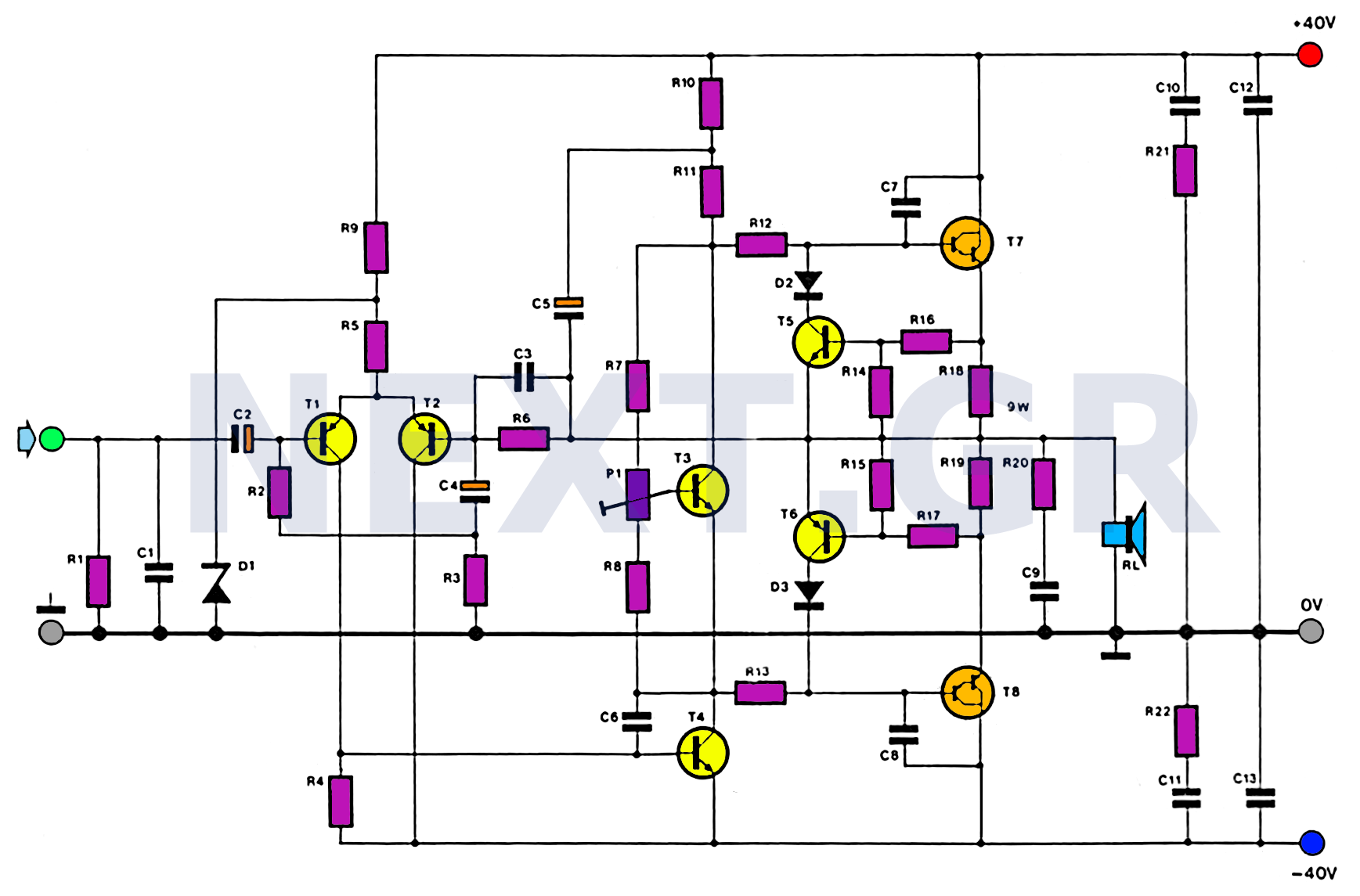
100W HiFi Audio Amplifier Circuit
This amplifier is designed with the following specifications: distortion less than 0.1% at full power of 100W even at 20KHz, with power attributed to an extended bandwidth. The output transistors are protected against short circuits, and the power supply is...

TDA1514 audio amplifier circuit design electronic project
The TDA1514 audio amplifier circuit design is an electronic project capable of delivering high audio power output using a specialized audio integrated circuit (IC) and a few common components. Manufactured by Philips Semiconductor, the TDA1514 audio IC can provide an...

audio amplifier with NE592
The broadband amplifier NE592 can be used also for building a simple selective audio amplifier. By means of the +6 V and +12 V supply voltages, a DC coupling between the product detector and the AF amplifier is possible. The...

1W BTL Audio Amplifier
The TDA8581(T) from Philips Semiconductors is a 1-watt Bridge Tied Load (BTL) audio power amplifier capable of delivering 1 watt of output power into an 8-ohm load at a total harmonic distortion (THD) of 10% while using a 5V power...

40 Watt Hi-Fi amplifier (TDA1514AN-7)
This high-quality audio amplifier is based on the TDA1514A, a 9-pin flat package integrated circuit. The heatsink must be insulated from the ground. The amplifier can deliver 40 watts into an 8-ohm load with a 27.5-volt power rail or 40...

10 Watt Audio Amplifier
This circuit is a general-purpose 10-W audio amplifier for moderate-power PA or modulator use in an AM transmitter. With higher voltages and a change in bias resistors, up to 30 W can be obtained.
The described audio amplifier circuit is designed...

50MW Audio Amplifier circuit
This weblog focuses on electronic circuit schematics, PCB design, DIY kits, and electronic project diagrams. The following describes a small audio amplifier, similar to those found in medium-sized transistor radios. The input stage is biased to ensure equal power distribution...
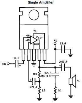
7W Mini Audio Amplifier Circuit based LM383
This is a simple mini audio amplifier circuit built around a single LM383 integrated circuit, along with several discrete components to support its operation. The circuit is capable of delivering approximately 7W of audio output. It can be constructed on...

2x30watt home amplifier circuit
The audio amplifier circuit is highly suitable for home use, particularly with subwoofer or woofer speakers. Commonly referred to as a home amplifier, these audio amplifiers are based on integrated circuits (ICs), specifically the STK series, which includes models such...