


Two-tones Siren with IC 4093
#siren
#IC 4093
#two-tone
#oscillator
#sound generator
#toys
#battery powered
#switches
#fun circuits
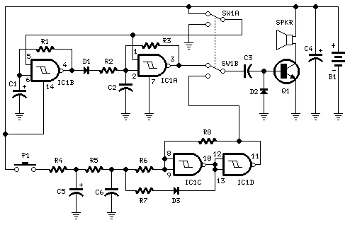
Description: This circuit is intended for children fun, and can be installed on bicycles, battery powered cars and motorcycles, but also on models and various games and toys. With SW1 positioned as shown in the circuit diagram, the typical dual-tone sound of Police or Fire-brigade cars is generated, by the oscillation of IC1A and IC1B gates. With SW1 set to the other position, the old siren sound increasing in frequency and then slowly decreasing is reproduced, by pushing on P1 that starts oscillation in IC1C and IC1D. More: The loudspeaker, driven by Q1, should be of reasonable dimensions and well encased, in order to obtain a more realistic and louder output. Tone and period of the sound oscillations can be varied by changing the values of C1, C2, C5, C6 and/or associated resistors.
The described circuit serves as an audio signal generator, specifically designed for entertainment purposes targeted at children. The circuit can be integrated into a variety of applications, such as bicycles, battery-powered vehicles, and toys, enhancing their play value through sound effects.
The core of the circuit consists of integrated circuits (IC1A, IC1B, IC1C, and IC1D), which function as oscillators to produce sound. The switch SW1 allows the user to select between two distinct sound modes. In one position, the circuit generates a dual-tone sound, reminiscent of emergency vehicles such as police cars or fire trucks. This is achieved through the interaction of the gates within IC1A and IC1B, which oscillate at specific frequencies to create the characteristic sound.
When SW1 is toggled to the alternate position, the circuit produces a siren-like sound that varies in frequency. This is initiated by pressing the pushbutton switch P1, which activates the oscillation of IC1C and IC1D. The frequency modulation of this siren sound provides an engaging auditory experience, as it starts at a higher frequency and gradually decreases, mimicking the sound of a distant siren.
The output of the circuit is amplified by transistor Q1, which drives a loudspeaker. It is recommended that the loudspeaker be of adequate size and enclosed properly to enhance sound quality and volume. The performance of the sound can be fine-tuned by adjusting the capacitance values of capacitors C1, C2, C5, and C6, as well as their associated resistors, allowing for customization of tone and duration of the sound effects produced.
Overall, this circuit design not only provides an enjoyable auditory experience but also encourages creativity and interaction in various play scenarios.This circuit is intended for children fun, and can be installed on bicycles, battery powered cars and motorcycles, but also on models and various games and toys. With SW1 positioned as shown in the circuit diagram, the typical dual-tone sound of Police or Fire-brigade cars is generated, by the oscillation of IC1A and IC1B gates.
With SW1 set to the other position, the old siren sound increasing in frequency and then slowly decreasing is reproduced, by pushing on P1 that starts oscillation in IC1C and IC1D. The loudspeaker, driven by Q1, should be of reasonable dimensions and well encased, in order to obtain a more realistic and louder output. Tone and period of the sound oscillations can be varied by changing the values of C1, C2, C5, C6 and/or associated r
The described circuit serves as an audio signal generator, specifically designed for entertainment purposes targeted at children. The circuit can be integrated into a variety of applications, such as bicycles, battery-powered vehicles, and toys, enhancing their play value through sound effects.
The core of the circuit consists of integrated circuits (IC1A, IC1B, IC1C, and IC1D), which function as oscillators to produce sound. The switch SW1 allows the user to select between two distinct sound modes. In one position, the circuit generates a dual-tone sound, reminiscent of emergency vehicles such as police cars or fire trucks. This is achieved through the interaction of the gates within IC1A and IC1B, which oscillate at specific frequencies to create the characteristic sound.
When SW1 is toggled to the alternate position, the circuit produces a siren-like sound that varies in frequency. This is initiated by pressing the pushbutton switch P1, which activates the oscillation of IC1C and IC1D. The frequency modulation of this siren sound provides an engaging auditory experience, as it starts at a higher frequency and gradually decreases, mimicking the sound of a distant siren.
The output of the circuit is amplified by transistor Q1, which drives a loudspeaker. It is recommended that the loudspeaker be of adequate size and enclosed properly to enhance sound quality and volume. The performance of the sound can be fine-tuned by adjusting the capacitance values of capacitors C1, C2, C5, and C6, as well as their associated resistors, allowing for customization of tone and duration of the sound effects produced.
Overall, this circuit design not only provides an enjoyable auditory experience but also encourages creativity and interaction in various play scenarios.This circuit is intended for children fun, and can be installed on bicycles, battery powered cars and motorcycles, but also on models and various games and toys. With SW1 positioned as shown in the circuit diagram, the typical dual-tone sound of Police or Fire-brigade cars is generated, by the oscillation of IC1A and IC1B gates.
With SW1 set to the other position, the old siren sound increasing in frequency and then slowly decreasing is reproduced, by pushing on P1 that starts oscillation in IC1C and IC1D. The loudspeaker, driven by Q1, should be of reasonable dimensions and well encased, in order to obtain a more realistic and louder output. Tone and period of the sound oscillations can be varied by changing the values of C1, C2, C5, C6 and/or associated r

Half-duty-cycle-oscillator
The frequency of oscillation depends on the Rl/Cl time constant, allowing for frequency adjustment by varying Rl. This is a basic circuit.
The described circuit operates based on the relationship between resistance (Rl) and capacitance (Cl), which together form a time...

Sonic Defender
This oscillator-driver produces a loud sound of approximately 3 kHz, modulated with a 10-Hz warble. BZ1 is a Matsushita EFB-RP3. U1A generates the 10-Hz waveform that modulates the 3-kHz tone produced by U1C and U1D. Q1 drives the transducer through...

Siren Alarm Circuit
The ramp voltage from the low-frequency oscillator IC1 modulates IC2, thereby producing a rising and falling tone similar to the wail of police cars.
The described circuit utilizes a low-frequency oscillator (IC1) to generate a ramp voltage. This ramp voltage serves...

Multitone Siren Alarm
This document presents a simple schematic of a multitone siren alarm circuit. The multitone siren is effective for reverse horns, burglar alarms, and various other applications. It generates five distinct audio tones, making it significantly more attention-grabbing than a single-tone...

Rf-genie
A variable oscillator operates in the frequency range of 3.2 to 22 MHz across two bands, enabling coverage from 80 meters to 15 meters, in addition to accommodating most crystal filter frequencies. Optional crystal oscillators at 455 kHz and 10.7...
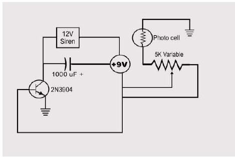
elp needed making changes circuit
Hello everyone, I am not well-versed in electronics, so I would appreciate it if someone could create a diagram for me. I would like to modify a circuit so that it can dial a number using speed dial and also...

Oscillators and Mixers
The emergence of modern radio and radar systems has created a demand for stable harmonic oscillations at specific carrier frequencies to facilitate the necessary modulation and mixing conditions. While early carrier frequencies primarily operated in the low to mid MHz...

Police siren
The circuit described here generates an alarm sound similar to a police siren. When the push button switch S2 is pressed, capacitor C1 charges, which gradually turns transistor Q1 ON. When switch S1 is released, capacitor C1 discharges, causing transistor...

Metal detector circuit diagram 3
The metal detector consists of a probe oscillator, a reference oscillator, an audio amplifier, and various other components, as illustrated in the schematic. The probe oscillator is made up of transistors V1 and V2, a detection coil L1, a capacitor...