


Ultra-Simple Mono-in Panning Mixer
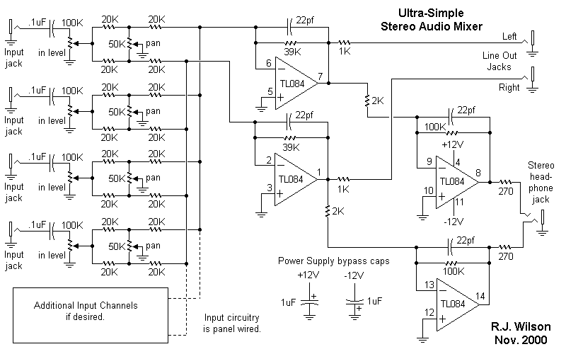
Description: This project represents an older design that has likely been replaced by a more recent version. Nonetheless, it remains a practical design suitable for a home-brew synthesizer. It is important to note that many of these designs lack circuit descriptions, parts lists, or printed circuit board (PCB) layouts, emphasizing the DIY aspect of the project. The designs are intended for individual and educational purposes only, and no permission is granted for large-scale production or sale. This project is categorized as intermediate to advanced, and it is not advisable for beginners who are just starting with synthesizers or electronics. Only the circuit and some explanations are provided, and a considerable amount of project building, troubleshooting, and electronics experience is assumed. Additionally, ownership of electronic equipment such as oscilloscopes and multimeters is expected. Prospective builders should thoroughly read the entire page before ordering PC boards to ensure that the information provided is adequate to successfully complete the project.
This synthesizer project involves a classic analog design that utilizes several key components, including operational amplifiers, voltage-controlled oscillators (VCOs), and filters. The circuit typically functions by generating audio signals through the VCOs, which produce waveforms that can be shaped and modulated. The output from the VCOs is then processed through various filters to create the desired sound characteristics.
The design may include a control voltage (CV) interface for modulation, allowing the user to manipulate pitch and timbre dynamically. Additionally, the synthesizer may feature a low-frequency oscillator (LFO) for modulation purposes, enabling effects such as vibrato or tremolo.
Given the complexity of the circuit, a thorough understanding of analog electronics is necessary. Builders should be familiar with concepts such as feedback loops, signal path design, and component selection to ensure optimal performance. The lack of a detailed parts list and PCB layout requires builders to be resourceful, sourcing components and designing their own layout based on the provided circuit diagram.
Testing and troubleshooting will be essential steps in the building process. It is recommended that builders utilize an oscilloscope and multimeter to monitor signal integrity and voltage levels at various points in the circuit. This will help in identifying any issues that may arise during assembly or operation.
In conclusion, while this synthesizer project is not suited for beginners, it offers an engaging opportunity for those with intermediate to advanced skills in electronics. Successful completion of the project will result in a functional synthesizer capable of producing a wide range of sounds, making it a valuable addition to any home studio.This project is an older design and has most likely been superceded by a newer one. However, it is still a viable design and useful for your home-brew synth. Sorry but most of these do not have circuit descriptions, parts lists or PC board layouts (They really put the `Y` in DIY). The designs are here for individual and educational use only and no permission is given for large scale production for sale. This is an intermediate to advanced project and I do not recommend it as a first project if you are just getting started in synths or electronics. Only the circuit and some explanation are shown here. A lot of project building, troubleshooting and electronics experience is assumed. Additionally, electronic equipment ownership (scope, meters, etc. ) is taken for granted. If you are interested in building this project please read the entire page before ordering PC boards to ensure that the information provided is thorough enough for you to complete the project successfully.
This synthesizer project involves a classic analog design that utilizes several key components, including operational amplifiers, voltage-controlled oscillators (VCOs), and filters. The circuit typically functions by generating audio signals through the VCOs, which produce waveforms that can be shaped and modulated. The output from the VCOs is then processed through various filters to create the desired sound characteristics.
The design may include a control voltage (CV) interface for modulation, allowing the user to manipulate pitch and timbre dynamically. Additionally, the synthesizer may feature a low-frequency oscillator (LFO) for modulation purposes, enabling effects such as vibrato or tremolo.
Given the complexity of the circuit, a thorough understanding of analog electronics is necessary. Builders should be familiar with concepts such as feedback loops, signal path design, and component selection to ensure optimal performance. The lack of a detailed parts list and PCB layout requires builders to be resourceful, sourcing components and designing their own layout based on the provided circuit diagram.
Testing and troubleshooting will be essential steps in the building process. It is recommended that builders utilize an oscilloscope and multimeter to monitor signal integrity and voltage levels at various points in the circuit. This will help in identifying any issues that may arise during assembly or operation.
In conclusion, while this synthesizer project is not suited for beginners, it offers an engaging opportunity for those with intermediate to advanced skills in electronics. Successful completion of the project will result in a functional synthesizer capable of producing a wide range of sounds, making it a valuable addition to any home studio.This project is an older design and has most likely been superceded by a newer one. However, it is still a viable design and useful for your home-brew synth. Sorry but most of these do not have circuit descriptions, parts lists or PC board layouts (They really put the `Y` in DIY). The designs are here for individual and educational use only and no permission is given for large scale production for sale. This is an intermediate to advanced project and I do not recommend it as a first project if you are just getting started in synths or electronics. Only the circuit and some explanation are shown here. A lot of project building, troubleshooting and electronics experience is assumed. Additionally, electronic equipment ownership (scope, meters, etc. ) is taken for granted. If you are interested in building this project please read the entire page before ordering PC boards to ensure that the information provided is thorough enough for you to complete the project successfully.

LM3900 Audio Mixer Schematic Diagram
This audio mixer circuit does not utilize a low impedance input to mix non-ideal sources; instead, it employs multiple amplifiers to provide ideal sources prior to mixing through simple resistors. An ideal source is characterized by low impedances, which ensures...

Simple mixer
This circuit was designed as a small portable DJ mixer for a friend. It is a simple audio mixer circuit featuring two dual logarithmic potentiometers to adjust input signal levels, along with several resistors for mixing. The circuit operates entirely...

3 channel audio mixer (2N3904)
That circuit will provide an overall gain of one between the output and each input channel. Each input channel includes a single 0.1uf capacitor and 100-Kilohms resistor to provide an output impedance of 100K. The number of input channels to...
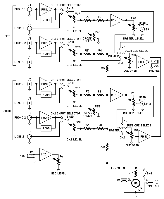
Compact DJ Station
The mixer features two stereo phono inputs and two stereo line-level inputs, along with one stereo bonded channel. Additionally, it includes a microphone input and a stereo output with adjustable gain.
The mixer is designed to facilitate audio mixing and processing...

Simple Mixer
This is a simple mixer featuring four inputs and two operational amplifiers (op-amps). It is designed for mixing microphone signals or effects outputs. The overall gain from input to output is unity when the potentiometer associated with the input is...
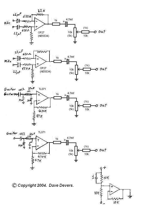
Guitar Microphone Mixer Electronic Audio Kit for musicians
The mixer is extremely useful for direct input (DI) of guitars and basses into soundcards or other mixers, allowing for the utilization of channels on mixers that lack microphone inputs. It is particularly beneficial for one or two guitarists who...

Two Channel Audio Mixer
It is often convenient to fade in or out or mix the inputs from two audio sources at any desired level. The circuit depicted is suitable for this purpose. One input connects to socket 1, and the second to socket...

4047/4066 audio slicer
You need to connect pins 1 and 13 of the 4053 to the virtual ground rail (top of C4), not the circuit's 0V rail.
The CD4053 is a triple 2-channel analog multiplexer/demultiplexer integrated circuit, widely used for routing analog signals...
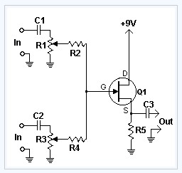
Fet Audio Mixer electronic circuit
This circuit combines two or more audio channels into a single channel (for example, converting stereo to mono). It is capable of mixing multiple channels while consuming minimal power. The schematic illustrates two inputs, but additional inputs can be incorporated...