


Wien-bridge-filter

Description: Most audio tone controls affect midband gain and often create booming or hissing sounds when activated. These problems can be avoided by using a dual Wien-bridge filter to provide independent control of the treble and bass frequencies. Experiments with equalizers indicate that the optimum center frequencies are approximately 100 Hz and 8 kHz. Using the relation f = (21fRC)^-1, set the values in Figure 1 accordingly: for 100 Hz, R1 = 15 kΩ and C1 = 0.1 µF; for 8 kHz, R2 = 16 kΩ and C2 = 1.3 nF. R3 and C3 provide stability. A ±9 dB variation of treble and bass can be achieved by adjusting potentiometers R4 and R5, respectively. The filter's frequency response is illustrated in Figure 2.
The dual Wien-bridge filter is an effective circuit design for audio tone control, providing a precise means of adjusting treble and bass frequencies without introducing undesirable artifacts such as booming or hissing sounds. This filter employs two separate branches, each tuned to the desired frequency range, allowing for independent adjustments.
The choice of center frequencies at 100 Hz for bass and 8 kHz for treble is based on empirical data from equalizer experiments, which suggest these points yield optimal sound quality for most audio applications. The resistors and capacitors used in the circuit are critical for determining the cutoff frequencies. The formula f = (21fRC)^-1 facilitates the calculation of these components. For the bass control, a resistor R1 of 15 kΩ paired with a capacitor C1 of 0.1 µF establishes the 100 Hz cutoff. Similarly, the treble control is set with a resistor R2 of 16 kΩ and a capacitor C2 of 1.3 nF to achieve the 8 kHz cutoff frequency.
To ensure stability in the filter operation, additional components R3 and C3 are incorporated, which help mitigate potential oscillations and maintain consistent performance across varying loads. The design allows for a treble and bass adjustment range of ±9 dB through the use of potentiometers R4 and R5, enabling fine-tuning of the audio output to suit individual preferences or specific acoustic environments.
The frequency response of the filter, as depicted in Figure 2, illustrates how the gain varies with frequency, confirming the effectiveness of the design in achieving the desired audio characteristics. This comprehensive approach to tone control ensures high fidelity and user satisfaction in audio applications.Most audio tone controls affect midband gain, and !bey often create booming or hissing sounds when activated. You can avoid tbese problems by using a dual Wien-bridge filter to provide independent control of tbe treble and bass frequencies.
Experiments witb equalizers indicate that tbe optimum center frequencies are about 100 Hz and 8 kHz. Using the relation/= (21fRC)-1, set the Fig. 1 values accordingly: 100Hz: R1 = 15 KO; C1 0.1 p,F 8kHz: R2 = 16 KO; C2 1.3 nF R3 and C3 provide stability. You obtain a ±9 dB variation of treble and bass by adjusting potentiometers R4 and R5, respectively.
The filter"s frequency response is shown in Fig. 2.
The dual Wien-bridge filter is an effective circuit design for audio tone control, providing a precise means of adjusting treble and bass frequencies without introducing undesirable artifacts such as booming or hissing sounds. This filter employs two separate branches, each tuned to the desired frequency range, allowing for independent adjustments.
The choice of center frequencies at 100 Hz for bass and 8 kHz for treble is based on empirical data from equalizer experiments, which suggest these points yield optimal sound quality for most audio applications. The resistors and capacitors used in the circuit are critical for determining the cutoff frequencies. The formula f = (21fRC)^-1 facilitates the calculation of these components. For the bass control, a resistor R1 of 15 kΩ paired with a capacitor C1 of 0.1 µF establishes the 100 Hz cutoff. Similarly, the treble control is set with a resistor R2 of 16 kΩ and a capacitor C2 of 1.3 nF to achieve the 8 kHz cutoff frequency.
To ensure stability in the filter operation, additional components R3 and C3 are incorporated, which help mitigate potential oscillations and maintain consistent performance across varying loads. The design allows for a treble and bass adjustment range of ±9 dB through the use of potentiometers R4 and R5, enabling fine-tuning of the audio output to suit individual preferences or specific acoustic environments.
The frequency response of the filter, as depicted in Figure 2, illustrates how the gain varies with frequency, confirming the effectiveness of the design in achieving the desired audio characteristics. This comprehensive approach to tone control ensures high fidelity and user satisfaction in audio applications.Most audio tone controls affect midband gain, and !bey often create booming or hissing sounds when activated. You can avoid tbese problems by using a dual Wien-bridge filter to provide independent control of tbe treble and bass frequencies.
Experiments witb equalizers indicate that tbe optimum center frequencies are about 100 Hz and 8 kHz. Using the relation/= (21fRC)-1, set the Fig. 1 values accordingly: 100Hz: R1 = 15 KO; C1 0.1 p,F 8kHz: R2 = 16 KO; C2 1.3 nF R3 and C3 provide stability. You obtain a ±9 dB variation of treble and bass by adjusting potentiometers R4 and R5, respectively.
The filter"s frequency response is shown in Fig. 2.

Music Equalizer Display Circuit
The music equalizer display schematic is relatively straightforward to construct. It can be assembled on a compact breadboard, utilizing the components listed previously. Due to the high number of connections required, it is advisable to have an ample supply of...
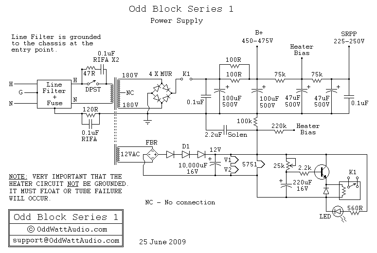
Audio Odd Block KT88 Series 1 Tube Amp-Power Supply
A schematic of the ability accumulation is presented below. Similar to the amplifier schematic, the ability accumulation design is © OddWatt Audio, and permission to host the schematic on this platform has been granted by OddWatt Audio. The schematic may...
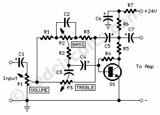
Tone ControlCircuit
P1 47K logarithmic potentiometer; P2, P3 47K linear potentiometers; R1, R3, R5 4.7K 1/4W resistors; R2 22K 1/4W resistor; R4 1M 1/4W resistor; R6 1.8K 1/4W resistor; R7 560Ω 1/4W resistor; C1, C4, C5, C7 10 µF 63V electrolytic capacitors;...

Zero Feedback Impedance Amplifiers
The amplifier in question is comparable to another model that has a lower parts count. It is worthy of construction.
The amplifier under discussion features a simplified design that maintains high performance while reducing the number of components required for assembly....
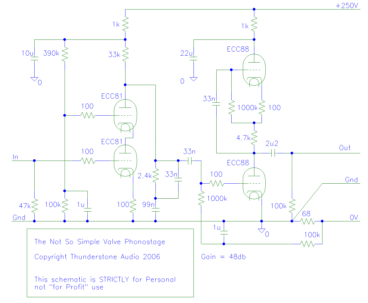
New Phono amp
Very interesting points Chris and Thorsten, but I would like to take a moment to revisit my latest design, which is represented in the attached schematic.
The attached schematic represents a recent design that integrates various electronic components to achieve a...

EUA2123 20-W Stereo Class-D Audio Power Amplifier
This application note describes the evaluation board for the AD7892-2, a 12-bit analog-to-digital (A/D) converter. The AD7892-2 is a high-speed, low-power device capable of 500 ksps sampling rate, operating from a single +5V supply. It features an on-chip track/hold amplifier,...
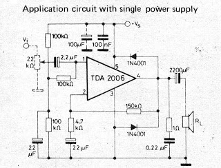
Small IC amplifiers for speakers
A small amplifier IC circuit has been compiled. This circuit is part of an older series and is categorized as a simple OTL (Output Transformer-Less) circuit.
The presented small amplifier IC circuit is designed for applications where compact size and simplicity...

Power amplifier 2X5W with TDA1516Q circuit
A simple stereo amplifier with minimal external components. It utilizes only one operational amplifier, which is capable of delivering an output power of 2x5W into a 4-ohm load, with a distortion of 0.5%.
This stereo amplifier circuit is designed to provide...

Simple 5 Band Equalizer Circuit
This circuit is a five-channel equalizer designed for a single line channel. The working principle of this series involves a series of frequency filters with a center frequency of 10 Hz.
The five-channel equalizer circuit is structured to manipulate audio signals...