


Auto Turn-Signal Reminder Circuit

Description: This circuit counts the flashes of turn signals. After approximately 70 flashes, a chime sounds to remind the driver to deactivate the turn signal. The period can be altered by using different taps on U2 if desired. BZ1 serves as a buzzer or chime module.
The turn signal counting circuit is designed to enhance vehicle safety by providing an auditory reminder to the driver, ensuring that turn signals are not left on unintentionally. The core of this circuit involves a microcontroller or timer IC (U2) that is configured to count the number of flashes emitted by the turn signal lights.
The circuit operates by monitoring the input from the turn signal circuit, typically through a phototransistor or a voltage divider that detects the on/off state of the turn signal. Each time the turn signal flashes, the microcontroller increments a counter. When the counter reaches a predetermined threshold of 70 flashes, the microcontroller activates the buzzer module (BZ1), which emits a chime sound. This auditory cue serves as a reminder for the driver to turn off the signal.
Furthermore, the design includes several taps on U2, which allow for flexibility in adjusting the counting period. By selecting different taps, the timing characteristics can be modified to suit various applications or user preferences. This feature is particularly useful in scenarios where the frequency of turn signal usage may vary, enabling customization for different vehicles or driving habits.
The buzzer module (BZ1) is typically a piezoelectric or electromagnetic type, capable of producing a loud enough sound to be heard over ambient noise. Its integration into the circuit is straightforward, requiring only a connection to the output pin of U2, which will provide the necessary drive signal when the counting threshold is reached.
Overall, this circuit represents a practical solution for improving driver awareness regarding turn signal usage, thereby contributing to safer driving practices. This circuit counts turn signal flashes. At the end of about 70 flashes, a chime sounds to remind the driver to turn off the turn signal. By using various taps on U2, the period can be changed if desired. BZ1 is a buzzer or chime module.
The turn signal counting circuit is designed to enhance vehicle safety by providing an auditory reminder to the driver, ensuring that turn signals are not left on unintentionally. The core of this circuit involves a microcontroller or timer IC (U2) that is configured to count the number of flashes emitted by the turn signal lights.
The circuit operates by monitoring the input from the turn signal circuit, typically through a phototransistor or a voltage divider that detects the on/off state of the turn signal. Each time the turn signal flashes, the microcontroller increments a counter. When the counter reaches a predetermined threshold of 70 flashes, the microcontroller activates the buzzer module (BZ1), which emits a chime sound. This auditory cue serves as a reminder for the driver to turn off the signal.
Furthermore, the design includes several taps on U2, which allow for flexibility in adjusting the counting period. By selecting different taps, the timing characteristics can be modified to suit various applications or user preferences. This feature is particularly useful in scenarios where the frequency of turn signal usage may vary, enabling customization for different vehicles or driving habits.
The buzzer module (BZ1) is typically a piezoelectric or electromagnetic type, capable of producing a loud enough sound to be heard over ambient noise. Its integration into the circuit is straightforward, requiring only a connection to the output pin of U2, which will provide the necessary drive signal when the counting threshold is reached.
Overall, this circuit represents a practical solution for improving driver awareness regarding turn signal usage, thereby contributing to safer driving practices. This circuit counts turn signal flashes. At the end of about 70 flashes, a chime sounds to remind the driver to turn off the turn signal. By using various taps on U2, the period can be changed if desired. BZ1 is a buzzer or chime module.

Time Switch
This circuit is specifically designed for individuals who frequently need to wake up early in the morning. Standard alarms in electronic watches are often insufficiently loud and frequently fail to wake users. The switch circuit described here will be useful;...

Divide-By-Odd-Number Counter
This circuit symmetrically divides an input by virtually any odd number. The circuit contains n + 1 clocks to achieve the desired divisor. By selecting the proper n, which is the decoded output of the 74LS161 counter, divisors from 3...

Bathroom Water Heater Timer
The electronic switch ES1 connects the frequency-determining capacitor to the input of clock oscillator N1. The logic level present at the Dm terminal of the integrated circuit is shifted to output Q at a speed defined by P1, allowing for...

Electronic Dice
When the switch SI is activated, the counter U2 is controlled by the oscillator U1A/U1B, and the count ranging from 0 to 6 is displayed on DISP1. The resistor R1 and capacitor C1 determine the count rate, which must be...

The Time Delay Circuit
The duration for which the circuit remains active is determined by the time required for the stored electrical current to leak back into the circuit, which keeps the transistor and the entire circuit energized. A resistor is present that limits...

Timing within the one-chip computer Counter and interrupt system
This document will present an overview of two critical components within a one-chip computer: the timing/counter system and the interrupt system. Through this explanation, readers will gain insight into the operating principles of these systems. For illustration, consider an alarm...

Self Retriggering Timed Generator Circuit
When power is first applied to the circuit, capacitor C2 begins to charge through LED1, resistor R3, and resistor R4. When the voltage across C2 reaches the input trigger level of operational amplifier U1, the output at pin 6 of...
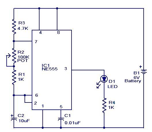
Mini Flasher
This is a simple and compact flasher circuit that can be used wherever a flashing LED is needed. The circuit is applicable in flashing beacons, alarms, automobiles, and more. It is essentially an astable multivibrator based on the NE555 integrated...

Repeating Timer 5
This timer circuit operates only when the temperature exceeds a predetermined level. An alternative version, known as Repeating Timer No. 6, functions while the temperature is below this preset level. The resistor R7 is used to set the temperature threshold....