


Automobile turn signal circuit
#turn signal
#TS 555 CN
#CD4017
#astable multivibrator
#decade counter
#sequential lighting
#automobile electronics
#timer IC
#counter IC
#signal light

Description: This is a simple circuit that can be used as a sequential signal light in automobiles. The circuit is based on two integrated circuits (ICs): a TS 555 CN CMOS timer IC and a CD4017 decade counter IC. The TS 555 is configured as an astable multivibrator to trigger the counter IC. When activated, the outputs of the CD4017 (pins 3, 2, 4, and 7) will sequentially go high and low. The speed of this sequencing is proportional to the triggering frequency. Transistors Q1 to Q4 drive the corresponding light-emitting diodes (LEDs). A switch (S1) is used to select the direction of the turn signal, and the LEDs arranged on the corresponding side of the vehicle will begin to sequence. The circuit is intended for use in creating sequential signal lights for the left and right rear of a motorcycle. It is proposed to use two of these circuits with half of the LEDs, eliminating the resistor R4 and the associated LEDs, and the switch S1 would not be necessary. The circuit would be energized when 12 volts is applied as the regular signal switch on the motorcycle handlebar is engaged. Additionally, the original equipment manufacturer (OEM) signal flasher would need to be bypassed, and a separate circuit for the front signal lights would be designed, which would consist of a simpler on/off flasher circuit for the LEDs in the front enclosures. The query pertains to the appropriate voltage and wattage of LEDs that can be used in this circuit, ensuring they are as bright or brighter than conventional 1156 lightbulbs.
The described circuit utilizes the TS 555 timer IC configured in astable mode to generate a continuous pulse signal, which serves as the clock input for the CD4017 decade counter IC. The CD4017 features ten output pins, but in this application, only four outputs (pins 3, 2, 4, and 7) are utilized for sequentially illuminating the LEDs. The frequency of the output pulse from the TS 555 determines the speed of the LED sequencing, allowing for customization based on user preference or specific application requirements.
Transistors Q1 to Q4 act as switches to control the current flowing through each LED. When a particular output pin from the CD4017 goes high, the corresponding transistor is activated, allowing current to flow through its associated LED, thus illuminating it. The arrangement of the LEDs should follow the vehicle's left and right turn signal configuration, ensuring that the correct side lights up in response to the turn signal activation.
The switch S1 is incorporated to facilitate the selection of the turn signal direction. When the switch is toggled, it will alter the triggering mechanism of the circuit, ensuring that the LEDs on the appropriate side are sequenced correctly.
For implementing this circuit on a motorcycle, two separate circuits can be employed for the left and right turn signals. By omitting certain components such as R4 and the switch S1, the design can be simplified while maintaining functionality. The circuit activation relies on the motorcycle's standard 12-volt signal switch, which engages the sequential light system when the turn signal is activated.
The design consideration for the front signal lights involves a simpler on/off flasher circuit, which can be achieved using a basic transistor switch configuration or a relay to toggle the front LEDs. This design ensures that the front indicators operate independently from the sequential rear lights.
Regarding the choice of LEDs, it is essential to select components with a forward voltage rating that aligns with the 12-volt supply. Commonly, 12V LEDs or those with a forward voltage of around 2-3V can be used, provided that appropriate current-limiting resistors are incorporated to prevent excess current from damaging the LEDs. The wattage of the LEDs should be considered to ensure they produce a brightness equivalent to or exceeding that of traditional 1156 light bulbs, which typically have a brightness output of around 150 lumens. Selecting high-brightness LEDs with a suitable lumen output, along with appropriate heat dissipation measures, will enhance visibility and performance in automotive applications.This is a simple circuit that can be used as a sequential signal light in automobiles. The circuit is based on two ICs. A TS 555 CN CMOS timer IC and a CD4017 decade counter IC. The IC1 is wired as an astable multivibrator to trigger the counter IC. When triggered, the outputs of the IC 2 (pins 3, 2, 4 and 7) will go high and low in sequence and t he speed of this sequencing will be proportional to the triggering frequency. The transistors Q1 to Q4 drives the corresponding LEDs. The switch S1 can be used to select the direction of turning and the LEDs arranged at the corresponding side of the vehicle will start sequencing. I would like to use this circuit to make sequencing signal lights left and right rear for my motorcycle.
I was thinking of using two of these circuits with 1/2 of the LEDs (eliminate the R4 part of the circuit and the LEDs attached and S1 would not be neccesary). Then the circuit would be energized when 12 volts was applied as the regular signal switch (on the motorcycle handlebar)was engaged.
I would have to bypass the OEM signal flasher and come up with a circuit for the front signal lights as well (These would be simpler just off/on flasher circuit for the leds in the front enclosures). The question that I have is what voltage and wattage of LEDs can I use in this circuit It would need to be as bright or brighter than conventional 1156 lightbulbs.
The described circuit utilizes the TS 555 timer IC configured in astable mode to generate a continuous pulse signal, which serves as the clock input for the CD4017 decade counter IC. The CD4017 features ten output pins, but in this application, only four outputs (pins 3, 2, 4, and 7) are utilized for sequentially illuminating the LEDs. The frequency of the output pulse from the TS 555 determines the speed of the LED sequencing, allowing for customization based on user preference or specific application requirements.
Transistors Q1 to Q4 act as switches to control the current flowing through each LED. When a particular output pin from the CD4017 goes high, the corresponding transistor is activated, allowing current to flow through its associated LED, thus illuminating it. The arrangement of the LEDs should follow the vehicle's left and right turn signal configuration, ensuring that the correct side lights up in response to the turn signal activation.
The switch S1 is incorporated to facilitate the selection of the turn signal direction. When the switch is toggled, it will alter the triggering mechanism of the circuit, ensuring that the LEDs on the appropriate side are sequenced correctly.
For implementing this circuit on a motorcycle, two separate circuits can be employed for the left and right turn signals. By omitting certain components such as R4 and the switch S1, the design can be simplified while maintaining functionality. The circuit activation relies on the motorcycle's standard 12-volt signal switch, which engages the sequential light system when the turn signal is activated.
The design consideration for the front signal lights involves a simpler on/off flasher circuit, which can be achieved using a basic transistor switch configuration or a relay to toggle the front LEDs. This design ensures that the front indicators operate independently from the sequential rear lights.
Regarding the choice of LEDs, it is essential to select components with a forward voltage rating that aligns with the 12-volt supply. Commonly, 12V LEDs or those with a forward voltage of around 2-3V can be used, provided that appropriate current-limiting resistors are incorporated to prevent excess current from damaging the LEDs. The wattage of the LEDs should be considered to ensure they produce a brightness equivalent to or exceeding that of traditional 1156 light bulbs, which typically have a brightness output of around 150 lumens. Selecting high-brightness LEDs with a suitable lumen output, along with appropriate heat dissipation measures, will enhance visibility and performance in automotive applications.This is a simple circuit that can be used as a sequential signal light in automobiles. The circuit is based on two ICs. A TS 555 CN CMOS timer IC and a CD4017 decade counter IC. The IC1 is wired as an astable multivibrator to trigger the counter IC. When triggered, the outputs of the IC 2 (pins 3, 2, 4 and 7) will go high and low in sequence and t he speed of this sequencing will be proportional to the triggering frequency. The transistors Q1 to Q4 drives the corresponding LEDs. The switch S1 can be used to select the direction of turning and the LEDs arranged at the corresponding side of the vehicle will start sequencing. I would like to use this circuit to make sequencing signal lights left and right rear for my motorcycle.
I was thinking of using two of these circuits with 1/2 of the LEDs (eliminate the R4 part of the circuit and the LEDs attached and S1 would not be neccesary). Then the circuit would be energized when 12 volts was applied as the regular signal switch (on the motorcycle handlebar)was engaged.
I would have to bypass the OEM signal flasher and come up with a circuit for the front signal lights as well (These would be simpler just off/on flasher circuit for the leds in the front enclosures). The question that I have is what voltage and wattage of LEDs can I use in this circuit It would need to be as bright or brighter than conventional 1156 lightbulbs.

Make this Astable Multivibrator Blinker Circuit Using NAND Gates
An astable multivibrator is an electronic configuration that generates continuous alternating high and low pulses from two outputs operating in tandem. The IC 4093 consists of four individual NAND gates in one package, specifically Schmitt trigger types, which provide hysteresis...

digital electronic lock
The digital lock utilizes four common logic integrated circuits (ICs) to manage a relay activation by inputting a four-digit code via a keypad. The initial four outputs from the CD4017 decade counter (pins 3, 2, 4, and 7) are combined...
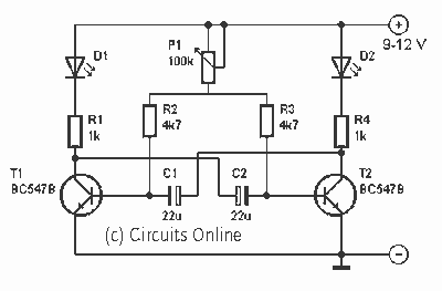
Astable multivibrator with two LED
This is one of the basic circuitry of the electronics. The multivibrator astable shows two LEDs alternately light up with an adjustable speed. The circuit uses two transistors conduct alternately by the capacitors charged and discharged. The rate at which...
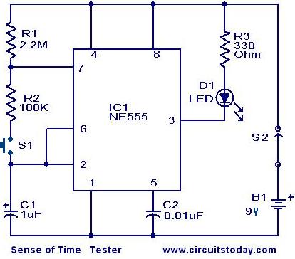
Sense of Time tester circuit
When switch S2 is activated, the circuit functions as an astable multivibrator, causing the LED to illuminate for approximately 0.1 seconds, flashing every 1.5 seconds. Due to the human reaction time being greater than this duration, it is unlikely to...

Clap Activated Remote With CD4017 IC
The disadvantage of infrared or wireless remote control is that the remote transmitter is often misplaced. This circuit design offers a way to control ...
This circuit design addresses the common issue of misplaced remote transmitters in infrared or wireless remote...
.png "One-touch turn signal module N version circuit")
One-touch turn signal module N version
The one-touch turn signal (OTTS) module enhances the functionality of the turn signal lever by adding a mode where a single touch makes the indicators blink for a certain number of times. This behavior is also known as lane change...

Smart Turn Signal Circuit
The STS schematic illustrates a circuit designed to alert a driver when the turn signal has been active for more than 15 seconds. The voltage at the gate of transistor Q2 increases in response to the charge accumulated on capacitor...

How does an astable multivibrator LED blinking circuit work
Blinks 2 LEDs in sequence. An explanation of its operation is requested. It is understood that a capacitor charges, causing the LED to turn off, and when it discharges, the LED turns on. However, clarification on the purpose of the...

Secure lock circuit (CD4017) schematic
The circuit consists of a two and four decimal counter CD4017 used in conjunction with a password switch. It is composed of the output terminals from the key switch logic combination of components, which provide another feature of the electronic...