


brake lights monitor

Description: The circuit described below monitors the car's brake lights and indicates their operational status using a light-emitting diode (LED). This functionality helps prevent fines for driving with defective brake lights and enhances road safety. The monitor relies on the voltage drop across the supply lines to the two lamps, which must exceed 0.6 V for proper operation. If the voltage drop is insufficient, a 5 V diode should be added in series with each lamp. Transistors T1 and T2 form a Schmitt trigger that responds to the voltage drop across the supply lines of the brake lights, causing the LED (D1) to illuminate via transistor T3. If one brake light is faulty, the current drawn by the functioning lamp will briefly light D1 when the brake pedal is pressed. If both brake lights are defective, D1 will remain off. This circuit thus indicates all three possible states of the brake lights. The hysteresis of the trigger, and consequently the circuit's sensitivity, can be fine-tuned with potentiometer P1, ideally adjusted with one lamp non-functional to ensure D1 lights briefly as described. If the user finds it undesirable for D1 to illuminate with every brake application, the operation can be inverted by substituting the BC557B transistor in the T3 position with a BC547B (n-p-n). In this configuration, the collector of T3 connects to the positive supply line, and the emitter connects to resistor R6. On the printed circuit board (PCB), this requires rotating T3's flat edge in the opposite direction. A second base connection is also available on the PCB; however, this adjustment will prevent determining whether one or both brake lights are faulty, as the LED will indicate that at least one lamp requires replacement when illuminated.
The circuit operates by monitoring the voltage across the brake light supply lines, utilizing a Schmitt trigger configuration with transistors T1 and T2. The Schmitt trigger provides a robust response to voltage variations, ensuring reliable detection of the brake light status. The presence of hysteresis in the trigger circuit allows for a clear distinction between on and off states, minimizing false triggering due to noise or minor fluctuations in voltage.
The LED indicator serves as a visual alert for the driver, enhancing safety by ensuring that brake lights are functioning correctly. The inclusion of a potentiometer (P1) allows for fine-tuning of the sensitivity, accommodating variations in lamp characteristics or supply voltage. This adjustability is critical, as it enables the user to set the threshold where the LED activates, ensuring that the circuit remains responsive without being overly sensitive to transient conditions.
The option to reverse the function of the LED by changing the transistor type provides flexibility in user preference. However, it is essential to note that this alteration affects the diagnostic capability of the circuit. In the original configuration, the LED's behavior allows for precise identification of which brake light is malfunctioning, thus facilitating timely repairs.
Overall, this circuit design combines practicality with safety considerations, providing a straightforward solution for monitoring brake light functionality in vehicles. The careful selection of components and design choices ensures reliability and ease of use, making it a valuable addition to automotive electronic systems.The circuit described below monitors your car`s brake lights, and indicates by a light emiting diode whether they both function correctly. In that sense, it can save you money by preventing your being fined for driving with defective brake lights, and it also leads to increasing road safety.
The monitor depends inevitably on the voltage drop acros s the supply lines to the two lamps. For the circuit to work correctly, that drop needs to be greater than 0. 6 V. If this is not so, the drop must be increased by adding a 5 V diode in series with each lamp. Transistor Ti and T2 in figure 1 form a Schmitt trigger, which reacts to the voltage drop across the supply lines to the two brake lights. This reaction manifests itself in Di lighting via T3. If one of the brake lights is faulty, the switch-on cur- rent drawn by the other lamp will cause Di to light briefly when the brake pedal is pressed.
If both brake lights are defective, Di will not light at all. All three possible states of the brake lights are thus indicated. The hysteresis of the trigger, and, therefore, the sensitivity of the circuit, can be adjusted within narrow limits with Pi. The preset is best adjusted with one lamp out of action in a manner which makes Di light briefly as described above.
If you find it disturbing that Di lights every time you brake, the operation can be reversed by replacing the BC557B in the T3 position by a BC547B (n-p-n). The collector of T3 is then connected to the positive supply line, and the emitter to R6. On the printed circuit board this means that the flat edge of T3 must be turned the other way. A second base connection has also been provided on the PCB. Note, however, that this configuration no longer makes it possible to ascertain whether one or both brake lights are faulty, i.
e. , when the LED lights, one or both lamps need replacing.
The circuit operates by monitoring the voltage across the brake light supply lines, utilizing a Schmitt trigger configuration with transistors T1 and T2. The Schmitt trigger provides a robust response to voltage variations, ensuring reliable detection of the brake light status. The presence of hysteresis in the trigger circuit allows for a clear distinction between on and off states, minimizing false triggering due to noise or minor fluctuations in voltage.
The LED indicator serves as a visual alert for the driver, enhancing safety by ensuring that brake lights are functioning correctly. The inclusion of a potentiometer (P1) allows for fine-tuning of the sensitivity, accommodating variations in lamp characteristics or supply voltage. This adjustability is critical, as it enables the user to set the threshold where the LED activates, ensuring that the circuit remains responsive without being overly sensitive to transient conditions.
The option to reverse the function of the LED by changing the transistor type provides flexibility in user preference. However, it is essential to note that this alteration affects the diagnostic capability of the circuit. In the original configuration, the LED's behavior allows for precise identification of which brake light is malfunctioning, thus facilitating timely repairs.
Overall, this circuit design combines practicality with safety considerations, providing a straightforward solution for monitoring brake light functionality in vehicles. The careful selection of components and design choices ensures reliability and ease of use, making it a valuable addition to automotive electronic systems.The circuit described below monitors your car`s brake lights, and indicates by a light emiting diode whether they both function correctly. In that sense, it can save you money by preventing your being fined for driving with defective brake lights, and it also leads to increasing road safety.
The monitor depends inevitably on the voltage drop acros s the supply lines to the two lamps. For the circuit to work correctly, that drop needs to be greater than 0. 6 V. If this is not so, the drop must be increased by adding a 5 V diode in series with each lamp. Transistor Ti and T2 in figure 1 form a Schmitt trigger, which reacts to the voltage drop across the supply lines to the two brake lights. This reaction manifests itself in Di lighting via T3. If one of the brake lights is faulty, the switch-on cur- rent drawn by the other lamp will cause Di to light briefly when the brake pedal is pressed.
If both brake lights are defective, Di will not light at all. All three possible states of the brake lights are thus indicated. The hysteresis of the trigger, and, therefore, the sensitivity of the circuit, can be adjusted within narrow limits with Pi. The preset is best adjusted with one lamp out of action in a manner which makes Di light briefly as described above.
If you find it disturbing that Di lights every time you brake, the operation can be reversed by replacing the BC557B in the T3 position by a BC547B (n-p-n). The collector of T3 is then connected to the positive supply line, and the emitter to R6. On the printed circuit board this means that the flat edge of T3 must be turned the other way. A second base connection has also been provided on the PCB. Note, however, that this configuration no longer makes it possible to ascertain whether one or both brake lights are faulty, i.
e. , when the LED lights, one or both lamps need replacing.

White LED Array Lamp
To create a battery-operated LED lamp, it is preferable to utilize a cluster of low-power discrete LED arrays instead of a single high-power LED. This configuration allows for scattered light production, significantly reducing irritation or potential damage to the eyes...

Mini Led Flashlight with LT1073 IC
This LED lamp circuit can be utilized as a mini LED flashlight. When paired with a 1.2 V rechargeable battery, all components can be housed within a compact enclosure.
The mini LED flashlight circuit typically consists of several key components: an...

256 Run LIght (for the 8bit bin to 256 / 1 of 256)
Switch S1 allows for direction change (Up/Down), Pot1 adjusts the clock speed, and LED D1 serves as an indicator for the clock speed.
The circuit utilizes a switch (S1) to control the direction of operation, allowing for two modes: upward and...

1.5V LED FLasher Using 3 Transistors
To make an LED function, a voltage source is required that exceeds the LED's forward bias voltage, which is typically greater than 1.5V (approximately 2V for red LEDs).
To effectively operate an LED, it is essential to provide a voltage source...

Mains Blinking LED
I needed a pulsating light for a certain signaling. Voltage was 230V. So I decided to make a simple circuit, consisted of a LED diode, two capacitors, two resistors, a diac and a diode. Activity of the circuit is extraordinarily...

power led driver
More:
A comprehensive electronic schematic involves the representation of electrical components and their interconnections in a circuit. Each component is typically represented by standardized symbols, and the connections between them are depicted using lines. The schematic provides essential information for...
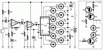
10 Dancing LEDs ElectronicCircuit Based On The LM358 IC
The following circuit illustrates a Dancing LEDs electronic circuit diagram. This circuit is based on the LM358 integrated circuit. Features: IC1A amplifies the signal.
The Dancing LEDs circuit utilizes the LM358 operational amplifier to create a visually appealing light display. The...
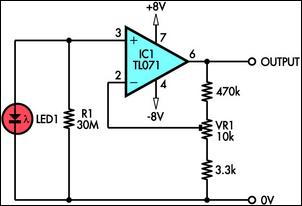
using led as a light sensor
This circuit demonstrates the use of a standard LED as a light sensor. It utilizes the photovoltaic voltage generated across the LED when exposed to light. LEDs are more cost-effective than photodiodes and feature an integrated filter, which is advantageous...
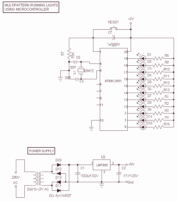
Multipattern Running LEDs
This Project Multi-Pattern Running light is used to generate several designs of Running Lights. We use ten LEDs for display. The designs can be selected by using two switches UP and DOWN. The 8 bit Microcontroller is used to control...