


Car Tachometer with 555 IC
#555 timer
#tachometer
#pulse measurement
#automotive electronics
#meter
#distributor
#calibration
#current measurement
#R6 resistor
#car instrumentation

Description: Pulses are received by the timer from the distributor points. When the timer output is high, Meter M receives a calibrated current through R6. The meter does not...
The circuit described involves a timer that receives pulse signals from distributor points, which are likely part of an ignition system in an automotive or similar application. The timer is responsible for processing these pulses and determining when to activate its output signal.
When the timer output is in a high state, it allows current to flow through a resistor, denoted as R6. This resistor is crucial as it helps to limit the current to a safe level for the meter, referred to as Meter M. The meter is designed to display a calibrated reading, which could represent various parameters such as voltage, current, or another measurement relevant to the system's operation.
The interaction between the timer and Meter M is essential for monitoring the system's performance. The calibrated current flowing through R6 ensures that the meter operates within its specified range, providing accurate readings. This functionality is critical in applications where precise measurements are necessary for system diagnostics or performance tuning.
Further analysis of the circuit may involve examining the specifications of the timer, the characteristics of the pulses being received, and the calibration details of Meter M. Additionally, understanding the role of R6, including its resistance value and power rating, will contribute to the overall reliability and accuracy of the circuit. Properly designed, this system can enhance the monitoring capabilities of the application it serves, ensuring optimal performance and safety.Pulses are received by the timer from the distributor points. When the timer output is high, Meter M receives a calibrated current through R6. The meter don`t..
The circuit described involves a timer that receives pulse signals from distributor points, which are likely part of an ignition system in an automotive or similar application. The timer is responsible for processing these pulses and determining when to activate its output signal.
When the timer output is in a high state, it allows current to flow through a resistor, denoted as R6. This resistor is crucial as it helps to limit the current to a safe level for the meter, referred to as Meter M. The meter is designed to display a calibrated reading, which could represent various parameters such as voltage, current, or another measurement relevant to the system's operation.
The interaction between the timer and Meter M is essential for monitoring the system's performance. The calibrated current flowing through R6 ensures that the meter operates within its specified range, providing accurate readings. This functionality is critical in applications where precise measurements are necessary for system diagnostics or performance tuning.
Further analysis of the circuit may involve examining the specifications of the timer, the characteristics of the pulses being received, and the calibration details of Meter M. Additionally, understanding the role of R6, including its resistance value and power rating, will contribute to the overall reliability and accuracy of the circuit. Properly designed, this system can enhance the monitoring capabilities of the application it serves, ensuring optimal performance and safety.Pulses are received by the timer from the distributor points. When the timer output is high, Meter M receives a calibrated current through R6. The meter don`t..

555 car circuit diagram of the device
The circuit diagram of the device features a 555 timer IC configured as a transmitter and a receiver, divided into two sections. The 555 timer in the transmitter section serves as the core component of a frequency oscillator. The oscillation...

5 to 30 Minute Timers
This circuit is simple to build and straightforward, but it requires the use of the CMOS type 555 timer designated as the 7555, as a standard 555 timer will not function properly due to the resistor values. A low leakage...

555 Timer IC for Square Wave Generator Application
The setup for the Square Wave Generator can be initiated using a 555 timer IC as illustrated in the accompanying circuit diagram. It is essential to reference the pinout configuration of the 555 timer IC. An oscilloscope should be connected...
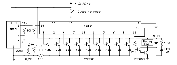
9 Second LED Timer and Relay
This circuit provides a visual 9-second delay using 10 LEDs before closing a 12-volt relay. When the reset switch is closed, the 4017 decade counter resets to the 0 count, illuminating the LED driven from pin 3. The 555 timer...

What do I need to close an electrical circuit for a certain amount of time
The old 555 timer will work based on the specifications provided, and it is a suitable choice if this is the exact problem to be addressed. As mentioned by Steven, this type of timing block is generally referred to as...

DC motor control using 555 timer circuit
This project utilizes a 555 timer to control the speed of a 6-volt DC motor. Speed adjustment is achieved by rotating a 50 kΩ potentiometer either to the left or right.
The circuit employs the 555 timer in astable mode, which...

Create a flash-then-steady LED using a 555 timer
The circuit illustrated briefly flashes an LED to attract attention and remains illuminated as long as power is supplied. The circuit utilizes the well-known 555 timer integrated circuit (IC) configured as a standard astable multivibrator with resistors RA, RB, and...

555 timer Electronic roulette wheel circuit and explanation
This electronic circuit is a simplified version of an electronic roulette game, utilizing the 4017 integrated circuit (IC), which functions as a 10-stage decade counter/divider. It is driven by a versatile 555 IC configured as a voltage-controlled oscillator (VCO). The...
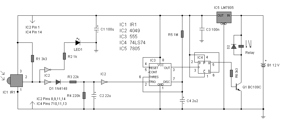
Single Channel Universal Infared Switch by 555 Timer
The circuit is designed to create a universal infrared switch with a single channel and ON/OFF functionality, operating in the frequency range of 36 kHz to 38 kHz, suitable for remote control applications. Infrared is a segment of the electromagnetic...