


Car windshield wiper delay
#windshield wiper
#delay circuit
#dynamic braking
#automotive
#wiper control
#safety
#driver vision
#switch
#MLS delay

Description: The circuit facilitates a windshield wiper delay, dynamic braking, and ensures that the windshield wipers return to their resting position. This design prevents the wiper blades from stopping at a location that could obstruct the driver's view. When the original wiper switch is off, a switch activates the MLS delay circuit and disconnects the SIB wiring from the vehicle. If the SI is turned off, the original wiring system is re-engaged, bypassing the delay circuit.
More: The SI operates using +12 V from the vehicle's battery, which is fed into a voltage doubler that generates +18 V. This elevated voltage is essential for reliably turning on transistor Q1 through the V2 multivibrator. The configuration provides approximately +18 V to the gate of Q1, with its source voltage being less than +12 V, accounting for the V_DS drop across Q1.
Transistor Q1 remains activated for a duration determined by the interval set by the WIPES potentiometer, which is adjusted by the pause control. When the capacitor C1 discharges below V + 4, the operational amplifier U2 is triggered, turning on Q1 and initiating the wiper cycle again.
The circuit employs a multivibrator configuration that ensures smooth operation of the windshield wipers, allowing for a controlled delay between wipes. The use of a voltage doubler not only enhances the voltage available for the control circuitry but also improves the responsiveness of the wiper system. The design is focused on safety and efficiency, ensuring that wiper blades return to a non-obstructive position while maintaining optimal visibility for the driver. The integration of the potentiometer allows for user customization of the wipe interval, adapting to varying weather conditions and driver preferences.The circuit provides a windshield wiper delay, dynamic braking and windshield wipers when they reach the rest position. This prevents the blades passing, which could lead them to stop at a point where they interfere with the vision of drivers.
With the original wiper switch off, switch turns on the MLS delay circuit and disconnects the wiring SIB from automobiles. When SI is turned off, the original wiring system and controls the delay circuit is bypassed. Regarding the SI uses the + 12 V to VI of the battery is a voltage doubler which produces + 18 V. This supply higher voltage is needed to ensure reliable turn on Ql through V2 multivibrator. This arrangement provides about +18 V to the gate of Ql, whose source is less than + 12 V drop V DS Ql. Ql stays on for a time determined by the interval between wipes WIPES potentiometervThe is controlled by the pause control when Cldrops below V + 4, U2 lights, turning on Ql and repeat the cycle.
More: The SI operates using +12 V from the vehicle's battery, which is fed into a voltage doubler that generates +18 V. This elevated voltage is essential for reliably turning on transistor Q1 through the V2 multivibrator. The configuration provides approximately +18 V to the gate of Q1, with its source voltage being less than +12 V, accounting for the V_DS drop across Q1.
Transistor Q1 remains activated for a duration determined by the interval set by the WIPES potentiometer, which is adjusted by the pause control. When the capacitor C1 discharges below V + 4, the operational amplifier U2 is triggered, turning on Q1 and initiating the wiper cycle again.
The circuit employs a multivibrator configuration that ensures smooth operation of the windshield wipers, allowing for a controlled delay between wipes. The use of a voltage doubler not only enhances the voltage available for the control circuitry but also improves the responsiveness of the wiper system. The design is focused on safety and efficiency, ensuring that wiper blades return to a non-obstructive position while maintaining optimal visibility for the driver. The integration of the potentiometer allows for user customization of the wipe interval, adapting to varying weather conditions and driver preferences.The circuit provides a windshield wiper delay, dynamic braking and windshield wipers when they reach the rest position. This prevents the blades passing, which could lead them to stop at a point where they interfere with the vision of drivers.
With the original wiper switch off, switch turns on the MLS delay circuit and disconnects the wiring SIB from automobiles. When SI is turned off, the original wiring system and controls the delay circuit is bypassed. Regarding the SI uses the + 12 V to VI of the battery is a voltage doubler which produces + 18 V. This supply higher voltage is needed to ensure reliable turn on Ql through V2 multivibrator. This arrangement provides about +18 V to the gate of Ql, whose source is less than + 12 V drop V DS Ql. Ql stays on for a time determined by the interval between wipes WIPES potentiometervThe is controlled by the pause control when Cldrops below V + 4, U2 lights, turning on Ql and repeat the cycle.

Conducting pipe control rechargeable delay circuit
The circuit features a delay action with an instantaneous reset control mechanism. It is categorized into three types: a conducting pipe rechargeable delay circuit, a tube cut-off control rechargeable delay circuit, and a discharge-type delay circuit. In the conducting pipe...

Delay On Circuit
Protect your LCD or Plasma TV with this small delay-on circuit. The SMPS-based power supply of these modern electronic devices is susceptible to voltage spikes.
This delay-on circuit is designed to enhance the protection of LCD and Plasma TVs by mitigating...
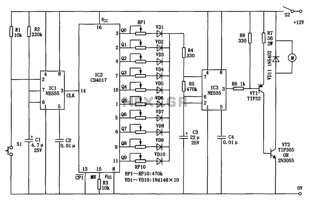
Automobile wiper speed control circuit diagram
The circuit for a car wiper speed controller allows for adjustable wiper speed, ranging from one to ten cycles per second. This feature enables flexibility in operation and contributes to energy efficiency.
The car wiper speed controller circuit typically employs a...

Five-way operation of the dynamic braking circuit
The circuit depicted in Figure 3-137 eliminates the need for a step-down transformer by utilizing the principle of energy storage capacitor discharge for braking. It can be employed to transform the power of motors with a rating of less than...

Discharge before memory circuit
Discharge before memory circuit. Before the memory circuit is activated, a delay reset circuit is required. When the input signal triggers an action, timing begins, and after a specified delay, the circuit reverts to its original state. During this interval,...

Automotive burglar alarm
The alarm activates after a 13-second delay and remains active for 1 to 1.5 minutes before automatically resetting. It can also be deactivated and reset by opening and reclosing switch SI.
The described circuit functions as a delay-triggered alarm system, incorporating...

Automotive Electrical Tester
This compact tester is designed for checking vehicle electrical circuits. Two LEDs indicate whether one of the clips is connected to the positive supply line (red) or to ground (green). The unit is powered by the vehicle battery. It is...
Discharge before memory circuit
Discharge before memory circuit. Before the memory circuit is activated, a delay reset circuit is required. When the input signal triggers an action, timing begins, and after a specified delay, the circuit reverts to its original state. During this interval,...

Three-way operation of the dynamic braking circuit
The circuit depicted in Figure 3-135 employs a time relay (KT) to determine the braking time.
The circuit utilizes a time relay, which is a crucial component for controlling the duration of the braking process. The time relay KT is designed...